Metrici Area Counter v2.0
User Manual for End Users and System Administrators

Table of Contents
- Getting Started
- Main Window Overview
- Video Source Configuration
- Setting Up Counting Zones
- Engine Working Mode and External Trigger
- External Trigger Configuration
- Reporting
- Signaling Device URL
- Live View Streaming
- Command Line Options
- Troubleshooting
Getting Started
Metrici Area Counter is a AI based software application that uses video cameras to automatically detect, recognize and count objects (people, vehicles, animals or any other object) as they move through defined areas. It's commonly used for attendance tracking, traffic monitoring, crowd management, and occupancy counting.
Starting the Application
The application automatically starts every time the sever is on. If not, launch the application from command line. The system will initialize and connect to your configured video source. If this is your first time running the application, you'll see a settings window where you can configure all your options.
Main Window Overview
The main window consists of several key areas:
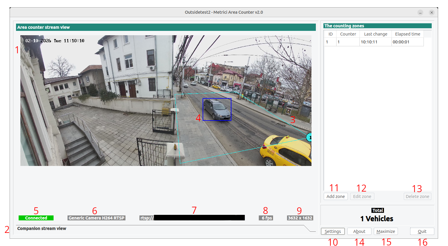
Video Display Area
The central area shows the processed video feed with:
- Main Stream: Your primary video source with detected objects and counting zones overlaid — see Fig.1 AC Interface (1).
- Companion Stream: (Optional) Secondary video source for alternative view. — see Fig.1 AC Interface (2).
- Zone Overlays: Semi-transparent polygons showing your counting zones — see Fig.1 AC Interface (3).
- Object Highlights: Bounding boxes around detected objects — see Fig.1 AC Interface (4).
Status Bar
Below the video, you'll see status information:
- Connection Status: Shows if camera is connected, disconnected, or connecting — see Fig.1 AC Interface (5).
- Stream Type: Type of video source (RTSP, HTTP, etc.)— see Fig.1 AC Interface (6).
- Stream Address: IP address or URL of the camera— see Fig.1 AC Interface (7).
- FPS: Frames per second being processed— see Fig.1 AC Interface (8).
- Resolution: Video resolution (width × height)— see Fig.1 AC Interface (9).
Control Buttons
- Settings: Opens the configuration window to adjust all settings — see Fig.1 AC Interface (10).
- Add Zone: Creates a new counting zone by drawing on the video. You can draw as many you want on each stream. — see Fig.1 AC Interface (11).
- Edit Zone: Modifies an existing counting zone — see Fig.1 AC Interface (12).
- Save Zone: Saves changes to counting zones, this button only apears after the Edit Zone is used — see Fig.1 AC Interface (12).
- Delete Zone: Removes the selected counting zone — see Fig.1 AC Interface (13).
- About: Shows version and license information — see Fig.1 AC Interface (14).
- Maximize: Toggles between full-screen and windowed mode — see Fig.1 AC Interface (15).
- Quit: Closes the application — see Fig.1 AC Interface (16).
Counters Display
The right panel shows:
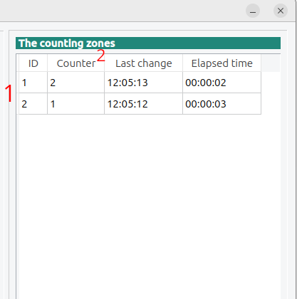
- Zone Table: List of all counting zones with their individual counts — see Fig.2 Counting zones (1).
- Total Counter: Sum of all objects counted across all zones — see Fig.2 Counting zones (2).
Video Source Configuration
The first and most important setup is configuring your video source. Click the Settings button to open the configuration window. — see Fig.1 AC Interface (10).
Input Stream
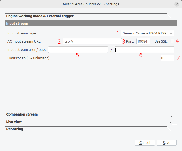
Stream Type
Select the type of video source from the dropdown menu — see Fig.3 Input Stream (1):
- ACTi: suported codecs: MJPEG, H264; standard protocols (HTTP, RTSP)
- Android: suported codecs: MJPEG; standard protocols (HTTP)
- Arecont Vision: suported codecs: MJPEG; standard protocols (HTTP)
- Axis: suported codecs: MJPEG, H264; standard protocols (HTTP, RTSP)
- BASLER: GigE
- Bosch: suported codecs: MJPEG, H264; standard protocols (RTSP)
- Dahua: suported codecs: MJPEG; standard protocols (HTTP)
- Divotec: suported codecs: MJPEG, H264; standard protocols (HTTP, RTSP)
- Hikvision: suported codecs: MJPEG, H264; standard protocols (HTTP, RTSP)
- Mobotix: suported codecs: MJPEG, MxPEG; standard protocols (HTTP)
- Novus: suported codecs: MJPEG, H264; standard protocols (HTTP, RTSP)
- Pelco: suported codecs: MJPEG; standard protocols (RTSP)
- Roseek: RAW
- Samsung:suported codecs: MJPEG, H264; standard protocols (HTTP, RTSP)
- VLC: suported codecs: MJPEG; standard protocols (HTTP)
- Vivotek: suported codecs: MJPEG; standard protocols (HTTP)
- Generic: suported codecs: MJPEG, H264; standard protocols (HTTP, RTSP)
Step-by-Step Setup:
- Click the Settings button on the main interface — see Fig.1 LC Main interface (10).
- Select "Input stream" from the settings categories — see Fig.3 Input Stream.
- Stream Type: Select your camera's protocol from the dropdown list — see. If your camera is not on list, just choose Generic. Fig.3 Input Stream (1).
- IP Address: Enter the camera's IP address — see Fig.3 Input Stream (2).
- Port: Enter the HTTP port (default HTTP is 80) - other protocols have different ports — see Fig.3 Input Stream (3).
- Use SSL: Enable if your camera requires secure connection — see Fig.3 Input Stream (4).
- Username/Password: Enter credentials if your camera is password protected — see Fig.3 Input Stream (5,6).
- Limit FPS: Set to 0 for unlimited, or specify a maximum frame rate — see Fig.3 Input Stream (7).
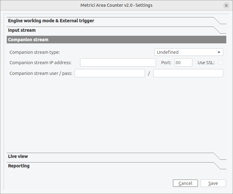
Companion Stream (Optional)
A secondary video source that can be used to have an alternative view of the scenery — see Fig.4 Companion. When a new event is registered by the main camera, a frame is saved from the companion one along the one with the detection. The companion stream uses the same configuration options as the main stream: type, address, authentication, ports, SSL, and resolution. Configure it independently based on your second camera's capabilities.
Setting Up Counting Zones
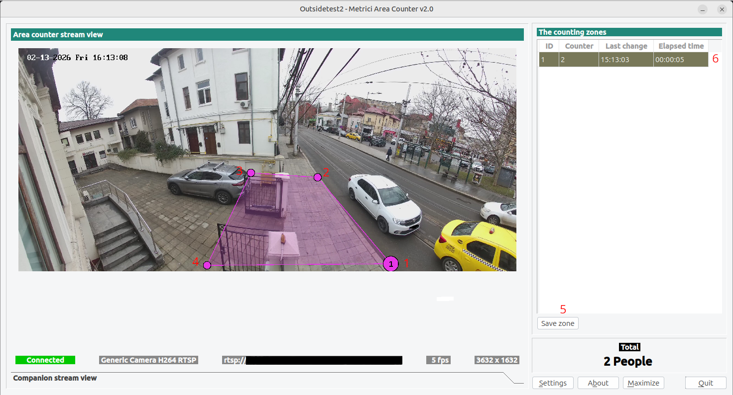
Counting zones are the areas where objects are detected and counted. Each zone is defined as a quadrilateral (four-sided polygon) on the video image.
Creating a New Zone
- Click the Add Zone button in the main window — see Fig.1 AC Interface (11).
- Drag on the four corners of the area you want to monitor. Click Save Zone.
- After placing all four points press save and the zone is created — see Fig.5 Area Zone (5).
- In an image, you can create as many zones as you want.
- Each zone will have a number on one of the corner indicating its order.
Zone Shape Guidelines
- Complete Coverage: Ensure the zone covers all paths where objects may be
Editing Existing Zones
- Select the zone from the zones table (click on it) — see Fig.5 Area Zone (6).
- Click the Edit Zone button — see Fig.1 AC Interface (12).
- Drag the corner points to new positions.
- Click Save Zone when finished .
Deleting Zones
- Select the zone from the zones table — see Fig.5 Area Zone (6).
- Click the Delete Zone button — see Fig.1 Area Zone (13).
- Confirm the deletion
Understanding Zone Counts
Each zone displays — see Fig.2 Counting zones:
- Zone ID: Unique identifier for the zone.
- Counter: Number of objects detected in this zone.
- Last Change: Timestamp of the most recent count change.
- Time Elapsed: Time since the zone was last modified.
Engine Working Mode and External Trigger
These settings control how the application detects and counts objects. Access them in Settings → Engine Working Mode and External Trigger
Engine Working Mode
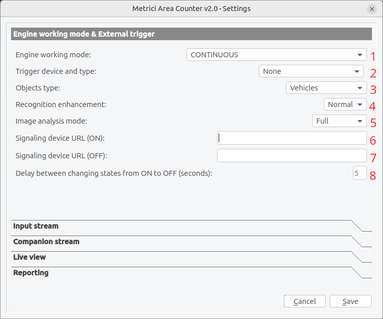
Choose how the detection engine should operate — see Fig.6 Engine working mode (1) :
| Mode | Description | Use Case |
|---|---|---|
| Continuous | Always processes video frames and counts objects | 24/7 monitoring, constant traffic areas |
| Started by Trigger, Ended After Time Period | Starts counting when triggered, stops after a set time | Less processing |
| Started by Trigger, Ended After Level Change | Starts counting when triggered, stops when trigger resets | Gate-triggered counting, door counters |
Recognition Enhancement
Applies additional image processing to improve detection and recognition accuracy. Enable this if objects are often missed or misidentified — see Fig.6 Engine working mode (4) . This setting adjusts detection accuracy across a range from Low to Ultra. Higher precision levels deliver significantly better results, though they do require more processing power. In most cases, a Normal setting will be sufficient — however, the smaller the objects appear in the video stream, the higher the accuracy needs to be, so High or even Ultra may be necessary.
| Level | Description | CPU Impact |
|---|---|---|
| Low | Minimal processing, fastest performance | Very Low |
| Medium | Balanced processing for moderate accuracy | Low |
| Normal | Standard processing for good accuracy | Medium |
| High | Aggressive processing for high accuracy | High |
| Ultra | Maximum processing for best accuracy | Very High |
| Insane | The top level of AI analysis | To use only in extreme situations |
Image Analysis Mode
Select the algorithm used for image analysis — see Fig.6 Engine working mode (5) :
- Full: The entire image is analyzed in one step. If the objects are smaller than 4% of the image, the image will be ignored.
- Cropped: Only the defined areas are cropped and analyzed one by one, so each object should be bigger than 4% of the corresponding cropped area.
- Microsope: The entire image is cropped in small tiles wich are analyzed one by one and the results are combined afterwards.
Object Type
Select what types of objects to detect and count — see Fig.6 Engine working mode (3) :
| Type | Description |
|---|---|
| People, People (fast) | Human detection only |
| Vehicles, Vehicles (fast) | Car, Truck, Bus, Semi-truck, Vans, SUV/pick-up, Motorcycle, Tram, other |
| People heads | Detect people heads |
| Boats | Jet-ski, Inflatable, Dinghy, Sailboat, Motor-yacht, Passenger-ship, Catamaran, other |
| Custom | Used in tailored projects when AI training is done for specific client's products/ objects |
The fast option reffers to a Metrici setting where a smaller DNN is used for faster processing when objects are bigger in the frame.
External Trigger Configuration
An external trigger allows you to start/stop counting based on external hardware signals, useful for integration with access control systems or sensors — see Fig.6 Engine working mode (2). If you don't have any external triggers leave it to None.
Trigger Types
| Trigger Type | Description |
|---|---|
| None | No external trigger, continuous operation |
| Barionet 50 I1-I4 | Barionet 50 controller inputs 1-4 (hardware I/O device) |
| Metrici Virtual | Software trigger from Metrici system |
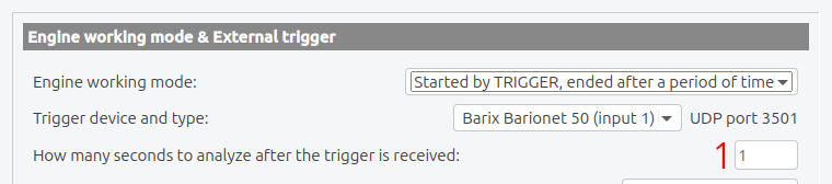
Trigger How Many Seconds to Analyze
How many seconds the engine analyzes the frames after the trigger is received. — see Fig.7 Seconds Delay.
Using Barionet Triggers
The Barionet 50 is a hardware I/O controller that provides digital inputs. Connect your trigger source (sensor, button, relay) to one of the four inputs:
- I1: Input 1 (typically GPIO1)
- I2: Input 2 (typically GPIO2)
- I3: Input 3 (typically GPIO3)
- I4: Input 4 (typically GPIO4)
Signaling Device URL
When configured, the system can send commands to open barriers based on counting events, object recognition, or external triggers. This enables automated access control systems.
Signaling Device URL ON
Enter the HTTP URL triggered when a new event is registered - the count in the area changes. This is typically a command sent to a controller or automation system — see Fig.6 Engine working mode (6):
Signaling Device URL OF
Enter the HTTP URL that triggers the stop of the process opened by the previous signal, like closing the barrier, a door, turning a light off etc — see Fig.6 Engine working mode (7):
Open-Close Delay
Sets how long (in seconds) the signal stays ON before automatically closing — see Fig.6 Engine working & External trigger (8):
RTSP Stream Latency
This setting can be set in .ini file rtsp_stream_latency = :
Set the buffering delay for RTSP streams. Higher values (500-2000ms) provide smoother video but increase delay between actual events and system response. For real-time counting, use lower values (100-300ms). By default the settings are set to (100-300ms).
RTSP Stream Protocol
This setting can be set in .ini file rtsp_stream_protocols= :
Choose which RTSP protocols to attempt. Using UDP is faster but may have issues through firewalls. TCP is more reliable but slightly slower. You can enable both to let the system try UDP first, then fall back to TCP if needed. The default RTSP protocol that is set is TCP.
Live View Streaming
Enable a live video stream that can be viewed in web browsers or other applications.
Enable Live View
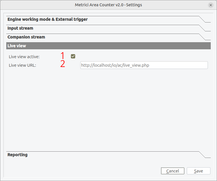
Check this box to enable live view streaming. When enabled, the processed video with overlays is made available for viewing — see Fig.8 Live View (1).
Live View URL
The local URL where the live stream is published. Default: http://localhost/io/ac/live_view.php
— see Fig.8 Live View (2).
To view the live stream, open a web browser and navigate to this URL. The stream will display the same view as the application main window.
Reporting
The application can send counting events to a remote server for recording.
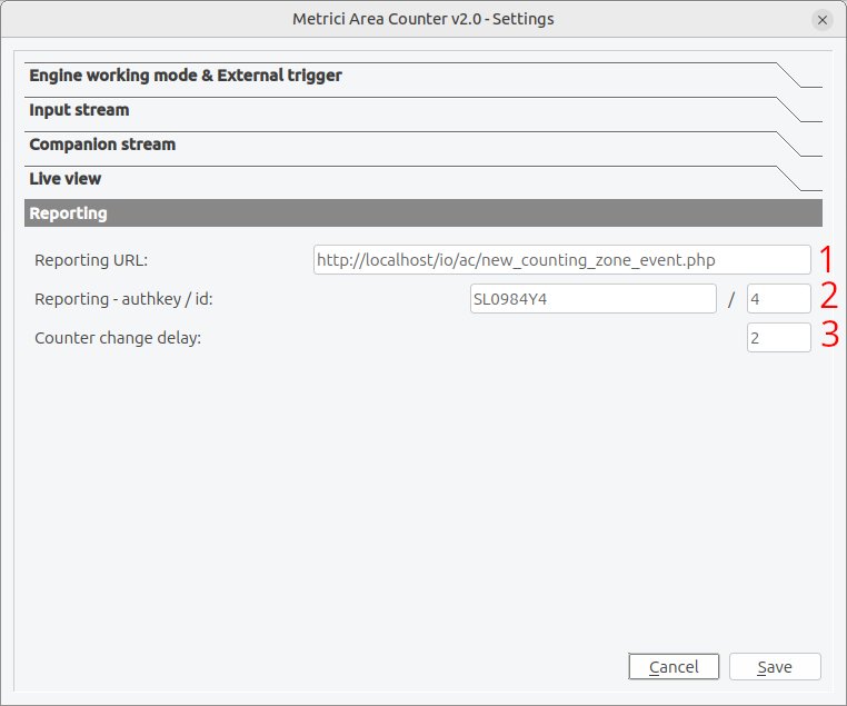
Reporting URL
The web address where counting events are sent. Format: http://localhost/io/ac/new_counting_zone_event.php — see Fig.9 Reporting (1)
When an object enters or exits a counting zone, the application sends an HTTP POST request with event data.
Check Action ID
An identifier sent with each event to help the server categorize or route the data. Leave as 0 if not used by your server.
This setting can be found in .ini file "reporting_check_action_id = 0" .
Authentication Key
The authkey and ID provide authentication for external server communications — see Fig.9 Reporting (2). These credentials are obtained from the Metrici web interface where you configure your AC cameras into the location. If not filled in, no database will be built, no access to events list, live view menu or check list and reporting detesctions on Interface.
Counter change delay
Sets a time delay (in seconds) between a detection event and the moment the counter is updated. This prevents false positives caused by brief, unintended triggers — for example, an object partially entering a zone and immediately moving back — see Fig.9 Reporting (3).
Duplicate URL (Optional)
An optional second URL where the same event data is sent (this URL can be set in .ini file). Use this for:
- Redundancy (backup server)
- Different processing (analytics + archive)
- Load balancing
Command Line Options
The application accepts several command line parameters for advanced configuration:- You must be in Metrici folder to use command line as below or enter the full path.
| Option | Description |
|---|---|
-nogui |
Run without graphical interface (headless mode) |
-app_id N |
Set application ID (uses config file N.ini). Default is 0. |
-app_name "Name" |
Set custom application name for display |
-detection_threads N |
Number of processing threads (1-8). Default is 1. |
-disable_gpu |
Disable GPU acceleration even if available |
-use_gpu N |
Force use of specific GPU device ID |
-log_level N |
Logging detail level: 0=None, 1=Low, 2=Medium, 3=High |
-v |
Display version information and exit |
Example Commands
# Run headless with application ID 5
./metrici-ac -nogui -app_id 5

# Run with 4 processing threads and high logging
./metrici-ac -detection_threads 4 -log_level 3

# Run with custom application name
./metrici-ac -app_name "Main Entrance Counter" -app_id 1

# Check version
./metrici-ac -v

# Run with GPU disabled (use CPU only)
./metrici-ac -disable_gpu
Troubleshooting
Connection Problems
"Camera Not Connecting"
Symptoms: Connection status shows "Disconnected", stream never connects
Solutions:
- Verify camera IP address is correct and camera is powered on
- Check network connectivity (ping the camera IP)
- Verify username and password are correct
- Ensure correct stream type is selected
- Check if camera requires HTTPS (enable SSL option)
- Try different TCP port (default 554 for RTSP, 80 for HTTP)
Detection Problems
"Objects Not Being Detected"
Symptoms: Video shows but no objects are highlighted or counted
Solutions:
- Ensure object type matches what you're trying to detect
- Increase recognition enhancement level
- Check if lighting is adequate
- Verify counting zones are properly drawn over the path
- Ensure objects are large enough in the frame
"False Positives (Ghost Counts)"
Symptoms: Count increases when nothing is there, or counts objects in wrong areas
Solutions:
- Increase recognition enhancement level
- Increase counter change delay
- Adjust counting zone boundaries to avoid background movement
- Check for shadows, reflections, or moving foliage in frame
- Change image analysis mode
Log Files
When troubleshooting, enable detailed logging to capture issues:
# Run with high logging level
./metrici-ac -log_level 3
Log files contain detailed information about:
- Connection attempts and results
- Detection events
- Count changes
- Error messages
Getting Help
If you continue to experience issues:
- Check the application logs (run with
-log_level 3) - Note the exact error messages and when they occur
- Record your configuration settings
- Contact technical support with:
- Application version
- Operating system
- Camera make and model
- Configuration file content
- Log file excerpts
Configuration File Reference
All settings are stored in configuration files (X.ini where X is the app ID). Here's a complete reference:
[General]
# Video Source Settings
input_stream_type=2                    # 0=None, 1=HTTP MJPEG, 2=RTSP H.264, etc.
input_stream_address=192.168.1.100     # Camera IP or URL
input_stream_tcp_port=554              # RTSP:554, HTTP:80
input_stream_use_ssl=0                 # 0=No, 1=Yes
input_stream_username=admin            # Camera login username
input_stream_password=password         # Camera login password
input_stream_fps_limit=0               # 0=Unlimited

# Companion Stream (Optional)
companion_stream_type=0
companion_stream_address=
companion_stream_tcp_port=80
companion_stream_use_ssl=0
companion_stream_username=
companion_stream_password=

# RTSP Settings
rtsp_stream_latency=2000               # Milliseconds (500-5000)
rtsp_stream_protocols=tcp              # tcp or udp

# Reporting Settings
reporting_url=http://localhost/io/ac/new_counting_zone_event.php #Default
reporting_duplicate_url=               # Optional backup server
reporting_check_action_id=0
reporting_check_action_authkey=        # Authentication key

# Live View Settings
live_view_active=1                     # 0=Off, 1=On
live_view_url=http://localhost/io/ac/live_view.php #Default

# Engine Settings
external_trigger_type=0                # 0=None, 1-4=Barionet inputs, 5=Virtual
external_trigger_seconds=1             # Trigger debounce time
engine_working_mode=0                  # 0=Continuous, 1=Time-triggered, 2=Level-triggered
recognition_enhancement=3              # 0=Low to 4=Ultra
image_analysis_mode=0                  # 0=Standard, 1=Enhanced, 2=Deep Learning
objects_type=2                         # 0=People, 1=Vehicles, 2=Both
counter_change_delay=2                 # Seconds

# Barrier Control
open_barrier_url=
close_barrier_url=
open_close_barrier_delay=5             # Seconds

# Counting Zones (Auto-generated, do not edit manually)
counting_zones_list="1,0.1,0.1,0.9,0.1,0.9,0.9,0.1,0.9;"
Glossary
| Term | Definition |
|---|---|
| RTSP | Real-Time Streaming Protocol - standard for streaming video over IP networks |
| H.264/H.265 | Video compression standards (also called AVC and HEVC) |
| MJPEG | Motion JPEG - format that sends individual JPEG images in sequence |
| FPS | Frames Per Second - rate at which video frames are captured/displayed |
| OpenCL | Open Computing Language - allows software to use GPU for processing |
| Latency | Delay between video capture and display |
| Authentication Key | Security code meant to facilitate communication between detection engines and database |
Technical Support
For additional help, please contact Metrici technical support team at support@metrici.ro.
Version: Metrici Area Counter v2.0