Metrici Line Counter
User Manual for End Users and System Administrators

Table of Contents
- Getting Started
- Main Window Overview
- Video Source Configuration
- Companion Stream
- Counting Lines
- Engine working Mode & External trigger
- Signaling Device URL
- External Trigger Setup
- GPS Calibration
- Reporting Configuration
- Live View Feature
- Troubleshooting
Getting Started
What This System Does
The Metrici Line Counter is an intelligent video analysis application that automatically detects and tracks various types of objects (vehicles, people, boats, animals, or custom objects) and counts them as they pass through virtual defined counting lines/ gates. It connects to your cameras, processes the video feed in real-time, and can send counting data to external systems or trigger automated responses.
The system is versatile and can be configured for numerous applications:
- Traffic monitoring: Count vehicles on roads, highways, or toll booths
- People counting: Monitor foot traffic in buildings, stores, sidewalk, or events
- Maritime applications: Count boats passing through locks or at harbors
- Industrial counting: Track items on production lines or in warehouses
- Wildlife monitoring: Count animals in conservation areas or farms
System Requirements
- Camera: IP camera or video file source
- Network: Stable connection for camera access (if using IP cameras)
- License Key: Valid HASP key for software activation
Starting the Application
The application automatically starts every time the sever is on. If not, launch the application from command line. The system will initialize and connect to your configured video source. If this is your first time running the application, you'll see a settings window where you can configure all your options.
Main Window Overview
The main window displays your video feed and provides access to all system controls. Understanding each section will help you operate the system efficiently.
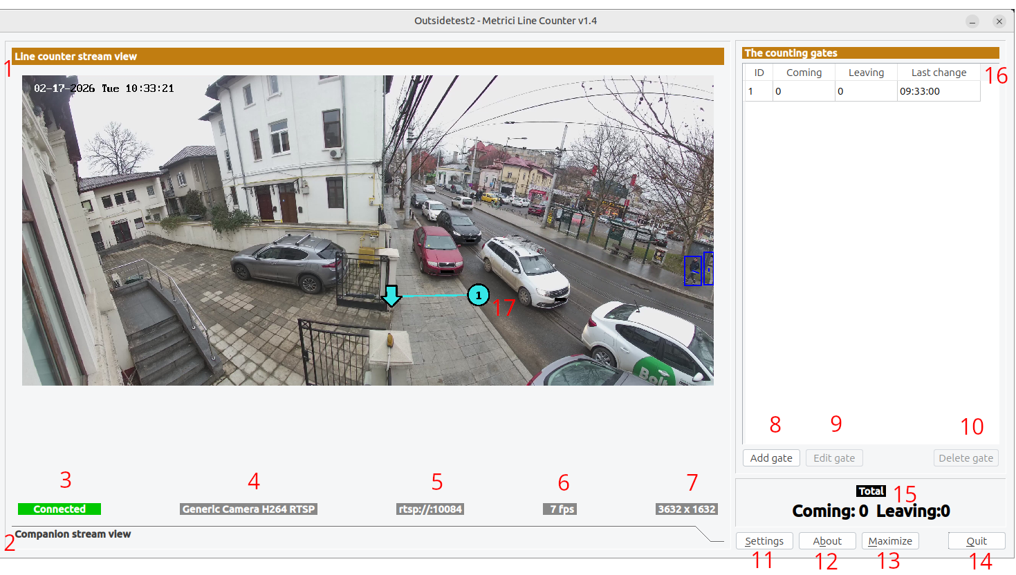
Video Display Area
The central area shows the processed video feed with:
- Main Stream: Your primary video source — see Fig.1 LC Main Interface (1).
- Companion Stream: (Optional) Secondary video source for alternative view — see Fig.1 LC Main Interface (2).
- Counting Lines: Virtual lines that detect when objects cross them — see Fig.1 LC Main Interface (17).
Status Bar
Below the video, you'll see status information:
- Connection Status: Shows if camera is connected, disconnected, or connecting — see Fig.1 LC Main Interface (3).
- Stream Type: Type of video source (RTSP, HTTP, etc.)— see Fig.1 LC Main Interface (4).
- Stream Address: IP address or URL of the camera— see Fig.1 LC Main Interface (5).
- FPS: Frames per second being processed— see Fig.1 LC Main Interface (6).
- Resolution: Video resolution (width × height)— see Fig.1 LC Main Interface (7).
Control Buttons
- Settings: Opens the configuration window to adjust all settings — see Fig.1 LC Main Interface (11).
- Add gate: Creates a new gate — see Fig.1 LC Main Interface (8).
- Edit Gate: Modifies an existing gate— see Fig.1 LC Main Interface (9).
- Delete Gate: Removes the selected gate— see Fig.1 LC Main Interface (10).
- About: Shows version and license information — see Fig.1 LC Main Interface (12).
- Maximize: Toggles between full-screen and windowed mode — see Fig.1 LC Main Interface (13).
- Quit: Closes the application — see Fig.1 LC Main Interface (14).
Video Source Configuration
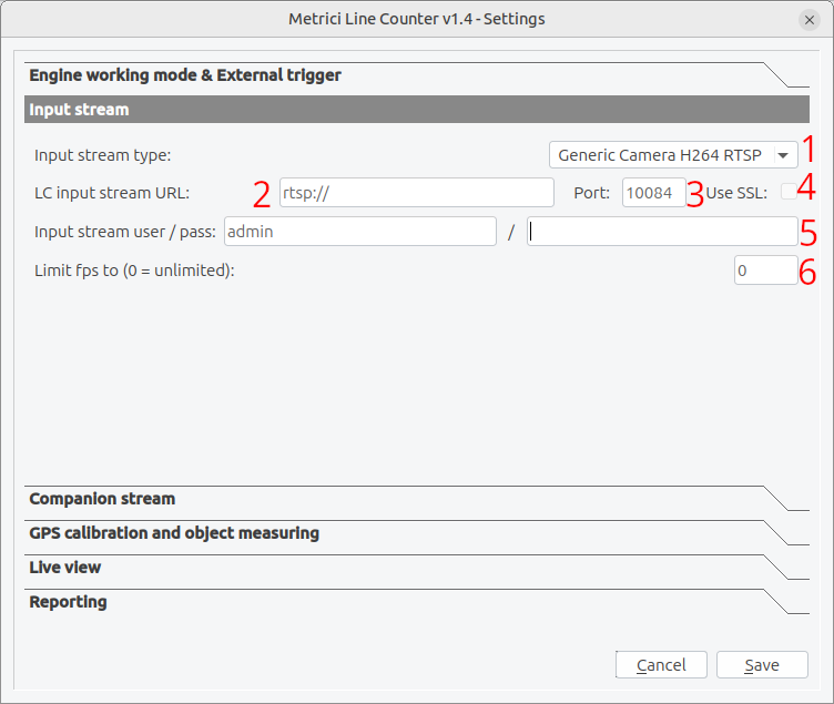
The first and most important setup is configuring your video source. Click the Settings button to open the configuration window — see Fig.1 LC Main Interface (11).
Input Stream type
The system includes optimized drivers for many popular camera brands:
- ACTi: suported codecs: MJPEG, H264; standard protocols (HTTP, RTSP)
- Android: suported codecs: MJPEG; standard protocols (HTTP)
- Arecont Vision: suported codecs: MJPEG; standard protocols (HTTP)
- Axis: suported codecs: MJPEG, H264; standard protocols (HTTP, RTSP)
- Bosch: suported codecs: MJPEG, H264; standard protocols (RTSP)
- Dahua: suported codecs: MJPEG; standard protocols (HTTP)
- Divotec: suported codecs: MJPEG, H264; standard protocols (HTTP, RTSP)
- Hikvision: suported codecs: MJPEG, H264; standard protocols (HTTP, RTSP)
- Mobotix: suported codecs: MJPEG, MxPEG; standard protocols (HTTP)
- Novus: suported codecs: MJPEG, H264; standard protocols (HTTP, RTSP)
- Pelco: suported codecs: MJPEG; standard protocols (RTSP)
- Roseek: RAW
- Samsung:suported codecs: MJPEG, H264; standard protocols (HTTP, RTSP)
- Sony:suported codecs: MJPEG, H264; standard protocols (HTTP, RTSP)
- Uniview:suported codecs: H264; standard protocols (HRTSP)
- VLC: suported codecs: MJPEG; standard protocols (HTTP)
- Vivotek: suported codecs: MJPEG; standard protocols (HTTP)
- Generic: suported codecs: MJPEG, H264; standard protocols (HTTP, RTSP)
Step-by-Step Setup:
- Click the Settings button on the main interface — see Fig.1 LC Main interface (11).
- Select "Input stream" from the settings categories — see Fig.2 Input Stream.
- Stream Type: Select your camera's protocol from the dropdown list — see Fig.2 Input Stream (1).
- IP Address: Enter the camera's IP address — see Fig.2 Input Stream (2).
- Port: Enter the HTTP port (default HTTP is 80) - other protocols have different ports — see Fig.2 Input Stream (3).
- Use SSL: Enable if your camera requires secure connection — see Fig.2 Input Stream (4).
- Username/Password: Enter credentials if your camera is password protected — see Fig.2 Input Stream (5).
- Limit FPS: Set to 0 for unlimited, or specify a maximum frame rate — see Fig.2 Input Stream (6). Line Counter needs more FPS to track the objects..
RTSP Stream Latency
These settings are done in the .ini file located in the metrici folder on the server.
Set the buffering delay for RTSP streams. Higher values (500-2000ms) provide smoother video but increase delay between actual events and system response. For real-time counting, use lower values (100-300ms). By default the settings are set to (100-300ms).
RTSP Protocol Selection
Choose which RTSP protocols to attempt. Using UDP is faster but may have issues through firewalls. TCP is more reliable but slightly slower. You can enable both to let the system try UDP first, then fall back to TCP if needed. The default RTSP protocol that is set is TCP.
Companion Stream
The companion stream feature allows you to connect a second camera that can provide additional viewpoints for verification.
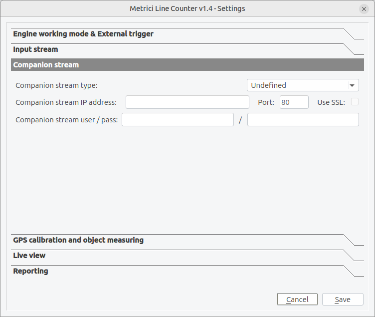
Use Companion Stream tab and fill in data only if one camera (different from LC one) is available for this purpose. Otherwise leave it blank.
Configuration Options
The companion stream uses the same configuration options as the main stream: type, address, authentication, ports, SSL, and resolution. Configure it independently based on your second camera's capabilities — see Fig.4 Companion.
When to Use Companion Stream
- Multiple angle capture: Main camera captures full view, companion gets detailed close-up. Every time an event is registered, an additional still frame is saved along the detection event photo
Counting Lines
Counting lines (also called "gates") are virtual lines drawn on your video image. Any time an object crosses them, Metrici AI detects it. This is how the system counts objects and determines direction of travel — see Fig.1 LC Main Interface (17).
Understanding Counting Lines
A counting line is a defined line on your video stream. When an object is detected crossing this line, the system records a counting event. You can configure multiple lines.
Adding a New Counting Line
- Click the Add Gate button in the main window — see Fig.1 LC Main Interface (8).
- A new counting line appears in the gates table.
- Drag the line endpoints to the desired location.
- Pay attention to the direction indicated by the arrow at the end of the gate. This registers the coming or going direction.
- Click Save Gate to confirm the position.
- You can add as many counting lines as you want in the application
Counting Line Properties
| Property | Description |
|---|---|
| Gate ID | Unique identifier for the counting line (automatically assigned) — see Fig.1 LC Main Interface (16). |
| Position (X1, Y1, X2, Y2) | Coordinates of the counting line endpoints (0-100% of image width/height). These data can be find in the .ini file of the aplication: gates_list="". |
| Counter Coming | Number of objects detected crossing in one direction — see Fig.1 LC Main Interface (16) . |
| Counter Leaving | Number of objects detected crossing in the opposite direction — see Fig.1 LC Main Interface (16). |
| Last Change | Timestamp of the most recent counting event — see Fig.1 LC Main Interface (16). |
Direction Detection
The system automatically determines object direction based on which side of the counting line the object was on before and after crossing. The counter increments in the appropriate direction (coming/leaving) based on this detection.
Deleting Counting Lines
Select a counting line in the table and click Delete Gate to remove it — see Fig.1 LC Main Interface (10). Confirm the deletion when prompted.
Testing Your Counting Lines
After positioning your counting lines, test them by having objects cross at different speeds and angles. Verify that the counts update correctly in both directions. Adjust line position if objects are missed or counted incorrectly.
Engine working Mode & External trigger
These settings control how the system detects and recognizes different types of objects. Proper configuration ensures accurate results for your specific application.
Objects type
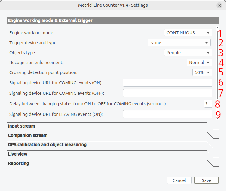
Specifies what types of objects the system should detect and track — see Fig.5 Engine working & External trigger (3):
- Vehicles: Cars, trucks, motorcycles, buses etc. Metrici has 9 classes of vehicle
- People: Will detect people or parts of human body
- People heads: Will only detect faces
- Boats: Jet-ski, Inflatable, Dinghy, Sailboat, Motor-yacht, Passenger-ship, Catamaran, Other
- Custom: Used in tailored projects when AI training is done for specific client's products/ objects
The fast option reffers to a Metrici setting where a smaller DNN is used for faster processing when objects are bigger in the frame.
Recognition Enhancement
Applies additional image processing to improve detection and recognition accuracy. Enable this if objects are often missed or misidentified — see Fig.5 Engine working & External trigger (4). What this will do is increase the accuracy of detection from Low to Ultra. The higher the precision, the more processing power is needed but the precision is much better. A normal setting would be just enough in most cases. The smaller the objects are in the video stream, the greater the accuracy must be so you will choose “high” or even “ultra”.
Engine Working Mode
From "Engine working mode:" — see Fig.5 Engine working & External trigger (1), you can choose between two options:
1. Continuous Mode
- Description: The system constantly analyzes every video frame
- Resource usage: High - uses more CPU/GPU
2. Triggered - Started by trigger
- Description: Detection starts when a trigger signal is received and continues for a set duration
- Saves: Processing power when no objects are present
Crossing Detection Point Position
Sets where on the object the system checks for line crossings — see Fig.5 Engine working & External trigger (5): A higher value means the crossing point will be computed to the top of the recognized object. 50% means crossing point is at half bounding box.
Signaling Device URL
This feature allows the system to automatically control equipment like bariers, gates or access control systems, typically used at entry points, toll stations, or secure facilities.
Understanding Signaling Device URL
When configured, the system can send commands to open barriers based on counting events, object recognition, or external triggers. This enables automated access control systems. The signal can be sent to other devices such as lights, audio signal, LED signs etc.
Signaling device for coming events (ON)
Enter the HTTP URL triggered when a new coming event is registered. This is typically a command sent to a controller or automation system — see Fig.5 Engine working & External trigger (6).
Signaling device for coming events (OFF)
Enter the HTTP URL that triggers the barrier/ equipment to close. The system can automatically close barriers after objects pass through — see Fig.5 Engine working & External trigger (7).
On-Off Delay
Sets how long (in seconds) the barrier/equipment stays open before automatically closing. Set this based on your typical traffic flow — see Fig.5 Engine working & External trigger (8).
Leaving events
If needed, do the same setting for leaving events too. Configure the secondary comand URLs and delays independently — see Fig.5 Engine working & External trigger (9).
External Trigger Setup
External triggers allow hardware devices or other systems to control the counting system. This is useful for integrating with sensors, signals, or external control systems.
An external trigger allows you to start/stop counting based on external hardware signals, useful for integration with access control systems or sensors — see Fig.5 Engine working & External trigger (2).
Trigger Types
| Trigger Type | Description |
|---|---|
| None | No external trigger, continuous operation |
| Barionet 50 I1-I4 | Barionet 50 controller inputs 1-4 (hardware I/O device) |
| Metrici Virtual | Software trigger from Metrici system |
Trigger Seconds
Sets how long (in seconds) the trigger must be active before it's recognized. This prevents noise or brief signals from triggering false events.
Using Barionet Triggers
The Barionet 50 is a hardware I/O controller that provides digital inputs. Connect your trigger source (sensor, button, relay) to one of the four inputs:
- I1: Input 1 (typically GPIO1)
- I2: Input 2 (typically GPIO2)
- I3: Input 3 (typically GPIO3)
- I4: Input 4 (typically GPIO4)
GPS Calibration
GPS calibration maps video image coordinates to real-world GPS coordinates. This allows the system to report actual positions of detected objects. Or measure object dimensions.
When to Use GPS Calibration
- Large areas requiring object location tracking.
- Outdoor monitoring systems needing geographic coordinates.
- Systems that integrate with fleet management or dispatch.
- Wildlife or maritime tracking applications.
- Measure objects entering an area - e.g. such as boats entering the port.
Calibration Process
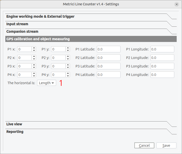
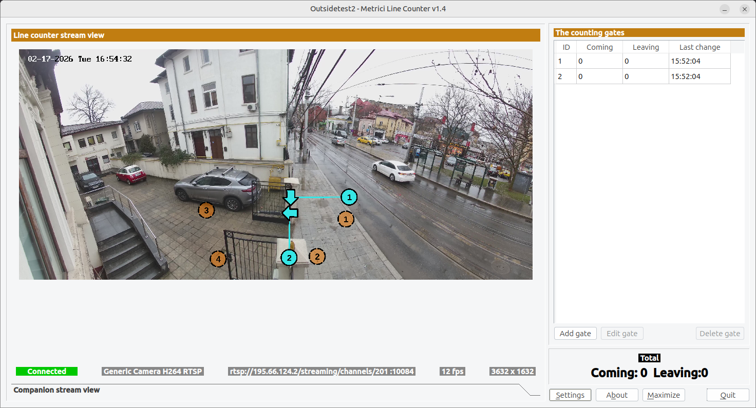
- Define 4 calibration points in the video image — see Fig.6.1 GPS Calibration.
- Measure the GPS coordinates (latitude/longitude) of each point in the real world.
- Enter the image coordinates and GPS coordinates in the settings— see Fig.6 GPS Settings.
- The system uses these points to calculate a transformation between image and GPS space.
Calibration Point Configuration
For each of the 4 calibration points, configure:
- X Coordinate: Horizontal position on image (0-100% from left to right)
- Y Coordinate: Vertical position on image (0-100% from top to bottom)
- Latitude: Real-world latitude of the point
- Longitude: Real-world longitude of the point
Horizontal Reference
Select the horizontal reference mode based on your camera angle — see Fig.6 GPS Settings (1):
- Length: Use when the horizontal reference line represents a measured distance along the scene (e.g., along the road/sidewalk direction). Sets scale for that axis.
- Width: Use when the horizontal reference line represents a measured distance across the scene (e.g., road/area width).
- Height: How tall an object is.
Reporting Configuration
Configure how the system sends counting data and events to external systems or databases.
Reporting URL
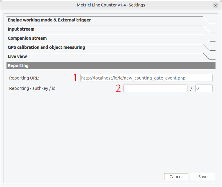
Enter the URL where the system should send counting data. Data is typically sent as HTTP POST requests with JSON or XML content — see Fig.7 Reporting (1):
http://server_ip/io/lc/new_counting_gate_event.phpDuplicate Reporting URL- .ini file setting
(Inside .ini file reporting_duplicate_url = Second_URL). Optionally specify a second URL to receive the same data.
Authentication Key
The authkey and ID provide authentication for external server communications — see Fig.7 Reporting (2). These credentials are obtained from the Metrici web interface where you configure your LC cameras into the location. Fill in here data obtained from Interface. This is how the detection engines build database and you have access to events in Interface, live view, reports etc.
Data Sent in Reports
Each counting event includes:
- Timestamp of the event
- Counting line ID that was crossed
- Direction of travel (coming/leaving)
- Object type (if recognized)
- Object image (if enabled)
- GPS coordinates (if calibrated)
Live View Feature
The live view feature allows remote viewing of the counting system's video output through a web browser or video streaming client.
Enabling Live View
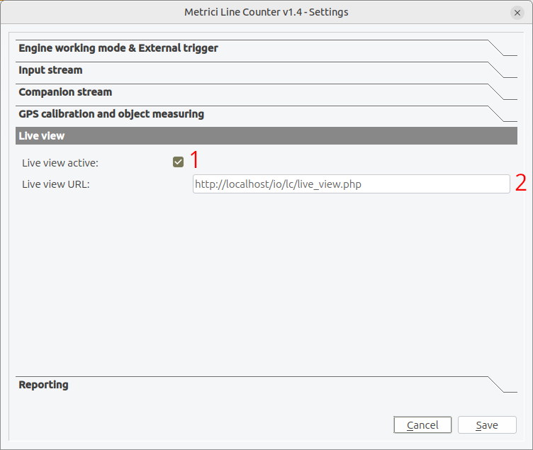
- Check Enable Live View in the settings — see Fig.8 Reporting (1).
- Enter the URL where the video stream should be published — see Fig.8 Reporting (2).
- Save the settings
Live View URL Configuration
The system can publish the processed video feed using various protocols. Common configurations:
server_ip/io/lc/live_view.phpTroubleshooting
Connection Issues
| Problem | Solution |
|---|---|
| Camera won't connect | Check network cable, verify IP address, confirm camera is powered on |
| Connection drops frequently | Increase RTSP latency, check network stability, reduce video quality |
| Wrong video stream | Verify stream address path, check camera configuration for correct stream |
| Authentication failed | Confirm username/password, check for special characters requiring URL encoding |
Counting Accuracy Issues
| Problem | Solution |
|---|---|
| Objects not counted | Reposition counting lines, Check recognition enhancement. Check crosspoint. |
| Wrong direction counted | Check line orientation |
Detection and Recognition Issues
| Problem | Solution |
|---|---|
| Objects not detected | Enable recognition enhancement, increase image resolution, improve lighting |
| Wrong object type detected | Check objects type setting, adjust recognition enhancement level |
| Slow detection | Reduce FPS limit, use faster stream type (RTSP H.264), upgrade hardware |
| Blurry images | Check camera focus, reduce motion blur with higher shutter speed |
Performance Issues
| Problem | Solution |
|---|---|
| Low frame rate | Reduce video resolution, lower FPS limit, disable enhancement features |
| High CPU usage | Use GPU acceleration if available, reduce number of counting lines |
| Memory usage growing | Restart application periodically, reduce video buffer sizes |
Barrier Control Issues
| Problem | Solution |
|---|---|
| Barrier not responding | Verify URL is correct, check barrier controller network connection, test URL manually |
| Barrier closes too fast | Increase open-close delay setting |
| Barrier opens unintentionally | Check trigger configuration, review external trigger settings |
Getting Help
If you continue experiencing issues:
- Check the application logs for detailed error messages
- Note the exact conditions when the problem occurs
- Contact technical support with:
- Application version
- Camera model and configuration
- Operating system details
- Error messages or log excerpts
Configuration File (INI File)
The Metrici Line Counter stores all its configuration settings in a file called [app_id].ini,
where [app_id] is the application identifier (typically a number). This file is created
automatically in the application directory when you first save your settings.
Understanding the INI File
The INI file is a standard configuration file format organized into key-value pairs. You can view or edit this file with any text editor, but it's recommended to use the application's Settings window for configuration changes to ensure all values are validated and saved correctly.
INI File Location
The INI file is stored in the same directory as the application executable. The filename matches
your application ID (e.g., 1.ini, 2.ini). Multiple INI files can exist
for different application instances.
Configuration Values Reference
The following table lists all configuration values stored in the INI file, their default values, and descriptions of what each setting controls.
Main Video Stream Settings
| Setting Name | Default Value | Description |
|---|---|---|
input_stream_type |
0 | Type of video stream (0=RTSP H.264, 1=RTSP H.265, 2=RTSP MJPEG, etc.) |
input_stream_address |
(empty) | Network address or file path of the video source |
input_stream_tcp_port |
80 | TCP port number for connecting to the camera |
input_stream_use_ssl |
0 | Enable SSL encryption for camera connection (0=off, 1=on) |
input_stream_username |
(empty) | Username for camera authentication |
input_stream_password |
(empty) | Password for camera authentication |
input_stream_fps_limit |
0 | Maximum frames per second to process (0=unlimited) |
input_stream_resx |
640 | Input video horizontal resolution in pixels |
input_stream_resy |
480 | Input video vertical resolution in pixels |
Companion Stream Settings
| Setting Name | Default Value | Description |
|---|---|---|
companion_stream_type |
0 | Type of companion video stream |
companion_stream_address |
(empty) | Network address or file path of the companion video source |
companion_stream_tcp_port |
80 | TCP port number for companion camera connection |
companion_stream_use_ssl |
0 | Enable SSL encryption for companion camera connection (0=off, 1=on) |
companion_stream_username |
(empty) | Username for companion camera authentication |
companion_stream_password |
(empty) | Password for companion camera authentication |
companion_stream_resx |
640 | Companion video horizontal resolution in pixels |
companion_stream_resy |
480 | Companion video vertical resolution in pixels |
RTSP Stream Settings
| Setting Name | Default Value | Description |
|---|---|---|
rtsp_stream_latency |
100 | Buffer delay in milliseconds for RTSP streams (100-2000ms) |
rtsp_stream_protocols |
tcp | RTSP transport protocols (tcp, udp, or both separated by comma) |
Object Detection Settings
normal_mode — default value: 1.
Setting this to 0 prevents the engine from incrementing the counter when the same person repeatedly crosses the counting line in either direction. Note that this only applies while the person remains visible in the camera frame — if they leave the field of view and re-enter, the engine will treat them as a new person on their next crossing.
| Setting Name | Default Value | Description |
|---|---|---|
recognition_enhancement |
2 | Image processing enhancement level (0=off, 1=standard, 2=high) |
objects_type |
1 | Type of objects to detect (all vehicles, people, custom categories) |
engine_working_mode |
0 | Recognition engine mode (0=speed, 1=balanced, 2=accuracy) |
crossing_detection_point_position |
5 | Which point on object triggers count (center, bottom, up, or else) |
Counting Lines Configuration
| Setting Name | Default Value | Description |
|---|---|---|
gates_list |
(empty) | List of configured counting lines with their positions and settings |
GPS Calibration Settings
| Setting Name | Default Value | Description |
|---|---|---|
gps_calibration_points |
1,0.2,0.2,0.0,0.0;2,0.8,0.2,0.0,0.0;3,0.8,0.8,0.0,0.0;4,0.2,0.8,0.0,0.0; | GPS calibration points (format: id,x,y,lat,lon;id,x,y,lat,lon;...) |
horizontal_is |
0 | Horizontal reference mode |
External Trigger Settings
| Setting Name | Default Value | Description |
|---|---|---|
external_trigger_type |
0 | Type of external trigger (0=none, 1=TCP, 2=UDP, 3=HTTP, 4=serial) |
external_trigger_seconds |
1 | Duration in seconds that external trigger remains active |
Reporting Settings
| Setting Name | Default Value | Description |
|---|---|---|
reporting_check_action_id |
0 | Identifier for this counting instance in reporting |
reporting_check_action_authkey |
(empty) | Security key for authenticating reporting requests |
reporting_url |
http://localhost/io/lc/new_counting_gate_event.php | URL where counting events are sent |
reporting_duplicate_url |
(empty) | Secondary URL for redundant reporting |
reporting_send_image |
1 | Include captured images in reports (0=no, 1=yes) |
Live View Settings
| Setting Name | Default Value | Description |
|---|---|---|
live_view_active |
1 | Enable live view streaming (0=disabled, 1=enabled) |
live_view_url |
http://localhost/io/lc/live_view.php | URL where the processed video stream is published |
Barrier Control Settings
| Setting Name | Default Value | Description |
|---|---|---|
open_barrier_url |
(empty) | HTTP URL that triggers the primary barrier to open |
close_barrier_url |
(empty) | HTTP URL that triggers the primary barrier to close |
open_close_barrier_delay |
5 | Seconds the primary barrier stays open before auto-closing |
open_barrier2_url |
(empty) | HTTP URL that triggers the secondary barrier to open |
close_barrier2_url |
(empty) | HTTP URL that triggers the secondary barrier to close |
open_close_barrier2_delay |
5 | Seconds the secondary barrier stays open before auto-closing |
Example INI File
Below is an example of what a typical INI file looks like with sample configuration values:
[General]
input_stream_type=0
input_stream_address=rtsp://192.168.1.100:554/stream1
input_stream_tcp_port=554
input_stream_use_ssl=0
input_stream_username=admin
input_stream_password=secret123
input_stream_fps_limit=25
input_stream_resx=1280
input_stream_resy=720
companion_stream_type=0
companion_stream_address=rtsp://192.168.1.101:554/stream1
companion_stream_tcp_port=554
companion_stream_use_ssl=0
companion_stream_username=
companion_stream_password=
companion_stream_resx=640
companion_stream_resy=480
rtsp_stream_latency=200
rtsp_stream_protocols=tcp
object_tracking_level=3
recognition_enhancement=1
objects_type=1
engine_working_mode=1
crossing_detection_point_position=5
normal_mode=1
gates_list=1,0.2,0.5,0.8,0.5;2,0.4,0.3,0.6,0.3;
gps_calibration_points=1,0.2,0.2,45.1234,12.5678;2,0.8,0.2,45.1240,12.5685;3,0.8,0.8,45.1230,12.5680;4,0.2,0.8,45.1225,12.5675;
horizontal_is=0
external_trigger_type=1
external_trigger_seconds=1
reporting_check_action_id=1
reporting_check_action_authkey=authkey123
reporting_url=http://server.io/lc/new_counting_gate_event.php
reporting_duplicate_url=
reporting_send_image=1
live_view_active=1
live_view_url=http://localhost/io/lc/live_view
open_barrier_url=
close_barrier_url=
open_close_barrier_delay=5
open_barrier2_url=
close_barrier2_url=
open_close_barrier2_delay=5Multiple Configuration Files
You can create multiple INI files for different configurations by changing the application ID. This is useful for:
- Different camera setups at different locations
- Testing new settings without affecting production configuration
- Switching between different counting scenarios
Simply copy the INI file with a different name and configure the application to use that file.
Glossary
- Counting Line (Gate)
- A virtual line on the video image used to detect object crossings for counting
- FPS
- Frames Per Second - Measure of video smoothness, higher values mean smoother video but more processing
- Object Tracking
- The process of following detected objects across consecutive video frames
- RTSP
- Real Time Streaming Protocol - Standard protocol for streaming video over networks
- SSL/TLS
- Encryption protocols for securing network communications
- Trigger
- A signal (from hardware or software) that causes the system to take action