Metrici Container Code Recognizer
Manual de utilizare pentru utilizatori finali și administratori de sistem

Cuprins
- Noțiuni introductive
- Prezentarea ferestrei principale
- Configurarea fluxului video- Input Stream
- Flux companion
- Fereastra de detecție
- Setări CCR
- Urmărirea direcției
- Mod de lucru și trigger extern
- Raportare și verificare acțiune
- Vizualizare live
- Barieră și semafor
- GPS
- Cântar
- Radar
- Depanare
Noțiuni introductive
Ce face acest sistem
Metrici Container Code Recognizer (CCR) este o aplicație AI de analiză video care detectează și citește automat codurile de identificare marcate pe containerele de transport intermodale. Se conectează la camera dumneavoastră, procesează imaginea în timp real și raportează fiecare cod de container recunoscut împreună cu un marcaj de timp. De asemenea, poate valida codul, îl poate transmite către sisteme externe și poate declanșa acțiuni automate, precum deschiderea unei bariere sau schimbarea unui semafor.
Codurile de container respectă standardul internațional ISO 6346. Un cod complet este format
dintr-un cod de proprietar, un identificator al categoriei de echipament, un număr de serie din șase cifre și o cifră de
control — de exemplu CFSU 000560 [1] — afișat de obicei împreună cu codul de dimensiune/tip (de exemplu 22G1).
Sistemul citește aceste caractere, validează cifra de control și stochează rezultatul. Consultați
Glosar pentru o descriere
completă a structurii codului.
Sistemul este utilizat în întreaga industrie de manipulare a containerelor:
- Port și terminale: Identifică containerele care intră sau ies pe camioane la poartă.
- Depozite și platforme de containere: Mențin un inventar exact al echipamentelor depozitate.
- Terminale feroviare: Citesc codurile de pe containerele transportate pe cale ferată sau pe șasiu.
- Cântare: Asociază codul recunoscut cu o greutate măsurată pentru fiecare container.
- Control acces: Permite sau refuză trecerea pe baza unui cod recunoscut și validat.
Cerințe de sistem
- Cameră: Cameră IP sau sursă de imagine/video poziționată pentru a capta clar codul containerului.
- Rețea: Conexiune stabilă pentru accesul la cameră (dacă folosiți camere IP).
- Cheie de licență: Cheie validă pentru activarea software-ului.
Pornirea aplicației
Aplicația se lansează automat la fiecare pornire a serverului. Motorul CCR se inițializează și se conectează la sursa video definită. La prima rulare, va fi necesar să configurați toate opțiunile în fereastra de setări.
Prezentarea ferestrei principale
Fereastra principală afișează fluxul video în stânga și rezultatele recunoașterii în dreapta. Înțelegerea fiecărei secțiuni vă va ajuta să operați sistemul în mod eficient.
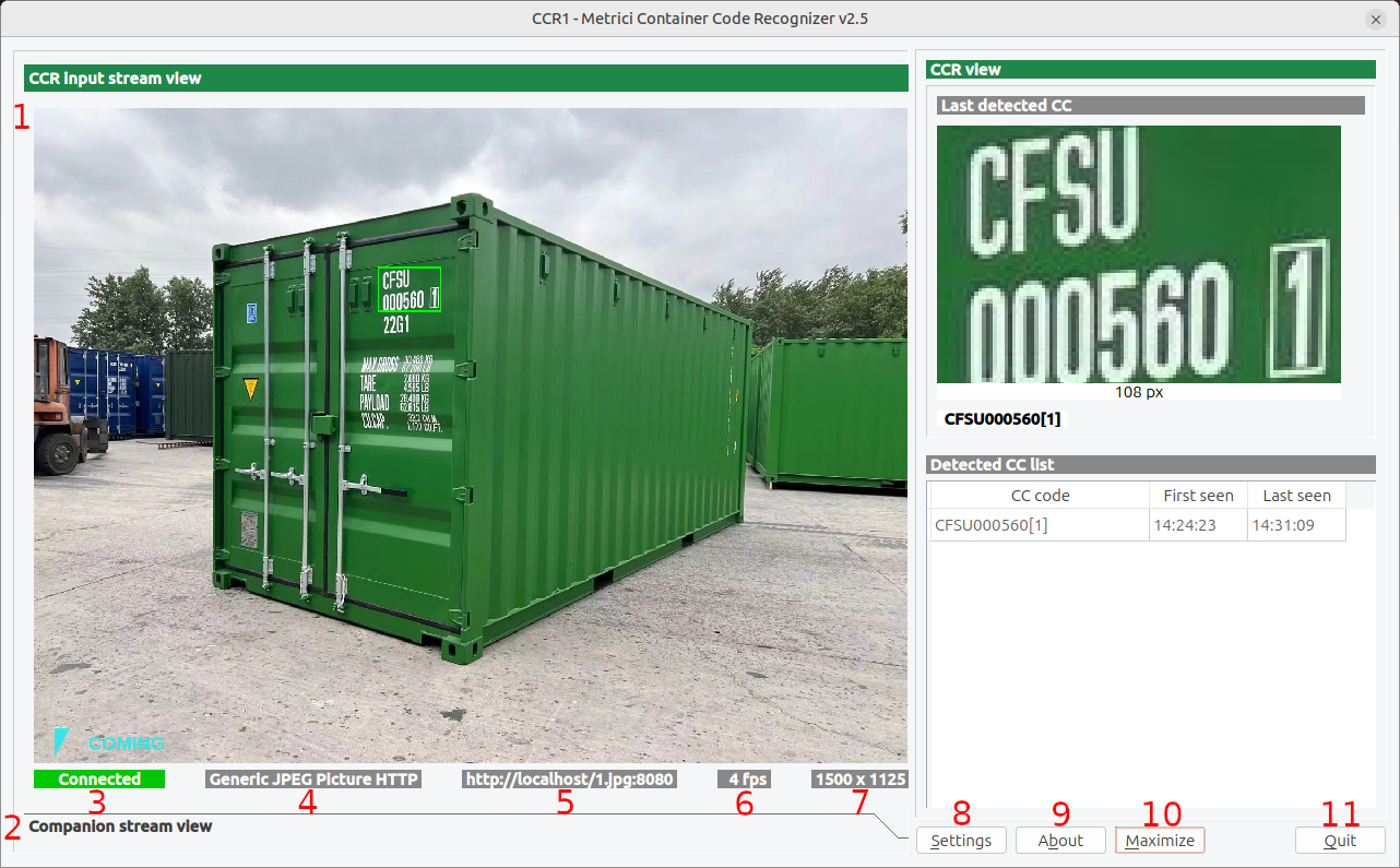
Zona de afișare video
Zona din stânga afișează fluxul video procesat, cu:
- CCR Input Stream View: Sursa video principală — vezi Fig.1 CCR Main Interface (1).
- Companion Stream View: (Opțional) Sursă video secundară pentru o perspectivă alternativă — vezi Fig.1 CCR Main Interface (2).
Bara de stare
Sub imaginea video, veți vedea informații de stare:
- Stare conexiune: Arată dacă camera este conectată, deconectată sau în curs de conectare — vezi Fig.1 CCR Main Interface (3).
- Tip flux: Tipul sursei video (Generic JPEG Picture HTTP, RTSP etc.) — vezi Fig.1 CCR Main Interface (4).
- Adresă flux: Adresa IP sau URL-ul camerei — vezi Fig.1 CCR Main Interface (5).
- FPS: Numărul de cadre pe secundă procesate — vezi Fig.1 CCR Main Interface (6).
- Rezoluție: Rezoluția video (lățime × înălțime) — vezi Fig.1 CCR Main Interface (7).
Rezultatele recunoașterii (CCR View)
Zona din dreapta afișează ce a citit motorul:
- Last detected CC: O imagine decupată a celui mai recent cod de container recunoscut,
lungimea în pixeli a acelui cod și textul decodat (de exemplu
CFSU000560[1]). Folosiți acest panou pentru a confirma că motorul citește corect codul. - Detected CC list: Un tabel cu codurile recunoscute, având coloanele CC code, First seen și Last seen. Fiecare rând înregistrează când a fost citit prima dată un cod de container și când a fost observat ultima dată.
Butoane de control
- Settings: Deschide fereastra de configurare pentru a ajusta toate setările — vezi Fig.1 CCR Main Interface (8).
- About: Afișează informații despre versiune și licență — vezi Fig.1 CCR Main Interface (9).
- Maximize: Comută între modul ecran complet și fereastră — vezi Fig.1 CCR Main Interface (10).
- Quit: Închide aplicația — aceasta va reporni daca este in modul Watchdog - vezi Fig.1 CCR Main Interface (11).
Configurarea fluxului video-Input Stream
Prima și cea mai importantă configurare este stabilirea sursei video. Apăsați butonul Settings pentru a deschide fereastra de configurare — vezi Fig.1 CCR Main Interface (8) — apoi deschideți secțiunea CCR input stream.
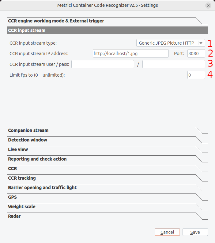
Tipul fluxului video = Input Stream
Selectați din meniu dropdown modul în care camera livrează imaginea si brandul vezi — Fig.2 CCR Input Stream (1). În cazul în care camera nu este pe listă va trebui ales Generic camera . Sistemul include, de asemenea, drivere optimizate si dedicate pentru multe mărci populare de camere:
- ACTi: codecuri acceptate: MJPEG, H264; protocoale standard (HTTP, RTSP)
- Android: codecuri acceptate: MJPEG; protocoale standard (HTTP)
- Arecont Vision: codecuri acceptate: MJPEG; protocoale standard (HTTP)
- Axis: codecuri acceptate: MJPEG, H264; protocoale standard (HTTP, RTSP)
- Bosch: codecuri acceptate: MJPEG, H264; protocoale standard (RTSP)
- Dahua: codecuri acceptate: MJPEG; protocoale standard (HTTP)
- Divotec: codecuri acceptate: MJPEG, H264; protocoale standard (HTTP, RTSP)
- Hikvision: codecuri acceptate: MJPEG, H264; protocoale standard (HTTP, RTSP)
- Mobotix: codecuri acceptate: MJPEG, MxPEG; protocoale standard (HTTP)
- Novus: codecuri acceptate: MJPEG, H264; protocoale standard (HTTP, RTSP)
- Pelco: codecuri acceptate: MJPEG; protocoale standard (RTSP)
- Roseek: RAW
- Samsung: codecuri acceptate: MJPEG, H264; protocoale standard (HTTP, RTSP)
- Sony: codecuri acceptate: MJPEG, H264; protocoale standard (HTTP, RTSP)
- Uniview: codecuri acceptate: H264; protocoale standard (RTSP)
- VLC: codecuri acceptate: MJPEG; protocoale standard (HTTP)
- Vivotek: codecuri acceptate: MJPEG; protocoale standard (HTTP)
- Generic: codecuri acceptate: MJPEG, H264; protocoale standard (HTTP, RTSP)
Configurarea pas cu pas a meniului CCR input stream:
- Apăsați butonul Settings din interfața principală — vezi Fig.1 CCR Main Interface (8).
- Selectați „CCR input stream” din categoriile de setări — vezi Fig.2 CCR Input Stream.
- Stream Type: Selectați protocolul camerei din listă — vezi Fig.2 CCR Input Stream (1).
- IP Address: Introduceți adresa IP a camerei — vezi Fig.2 CCR Input Stream (2).
- Port: Introduceți portul (pentru HTTP implicit este 80) — alte protocoale folosesc porturi diferite — vezi Fig.2 CCR Input Stream (2).
- Username/Password: Introduceți datele de autentificare dacă aveți camera protejată cu parolă — vezi Fig.2 CCR Input Stream (3).
- Limit FPS: Setați la 0 pentru un număr de cadre nelimitat sau specificați o rată maximă — vezi Fig.2 CCR Input Stream (4). Deoarece containerele trec lent printr-o poartă, nu este necesară o rată de cadre ridicată; limitarea FPS reduce încărcarea fără a afecta acuratețea.
Latența fluxului RTSP
Setările de alegere a protocolului RTSP și latența fluxului se fac în fișierul ID.ini al enginului (de exemplu 0.ini, 1.ini etc). Acest fișier se găseste în folderul unde a fost instalat software-ul Metrici.
Setarea de schimbare a fluxului apare în fișierul .ini ca rtsp_stream_latency. Când se folosește o cameră RTSP, se poate seta întârzierea de buffer. Valorile mai mari (500-2000ms) oferă un video mai fluid, dar
măresc întârzierea dintre evenimentele reale și răspunsul sistemului. Pentru recunoaștere în timp real, folosiți valori mai mici
(100-300ms). În mod implicit, setările sunt (100-300ms).
Selectarea protocolului RTSP
Setarea de schimbare a protocolului apare în fișierul .ini ca ca rtsp_stream_protocols. Alegeți ce protocoale RTSP să fie încercate. UDP este mai rapid, dar poate avea probleme prin firewall-uri. TCP este
mai fiabil, dar puțin mai lent. Le puteți activa pe ambele pentru ca sistemul să încerce mai întâi UDP, apoi să revină la TCP
dacă este necesar. Protocolul RTSP setat implicit este TCP.
Companion stream
Completați secțiunea Companion Stream doar dacă dispuneți de o a doua cameră, distinctă de cea CCR, dedicată acestui scop. În caz contrar, lăsați câmpurile necompletate.
Funcția de flux companion vă permite să conectați o a doua cameră care poate oferi o perspectivă suplimentară pentru verificare.
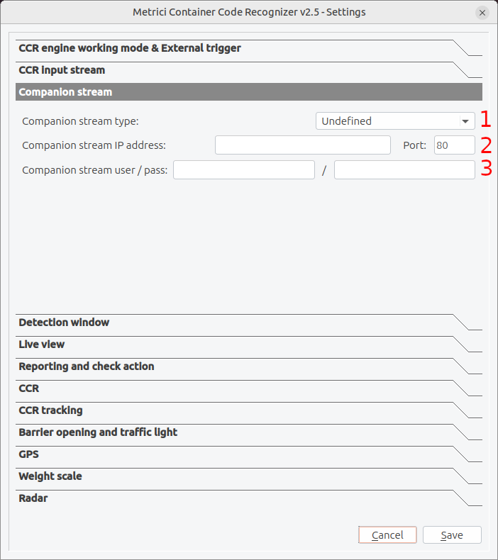
Opțiuni de configurare
Fluxul companion folosește aceleași opțiuni de configurare ca fluxul principal: tip, adresă, autentificare și port. Configurați-l independent, în funcție de capabilitățile celei de-a doua camere — vezi câmpurile pentru Companion stream type Fig.3 Companion Stream (1), IP address / Port Fig.3 Companion Stream (2) and user / pass Fig.3 Companion Stream (3).
Fereastra de detecție - Detection window
Fereastra de detecție vă permite să definiți o zonă specifică în cadrul imaginii camerei unde sistemul va căuta coduri de container. Aceasta este esențială pentru îmbunătățirea preciziei și reducerea detecțiilor false din zonele în care codurile nu pot fi detectate corect. — vezi Fig.4 Detection Window.
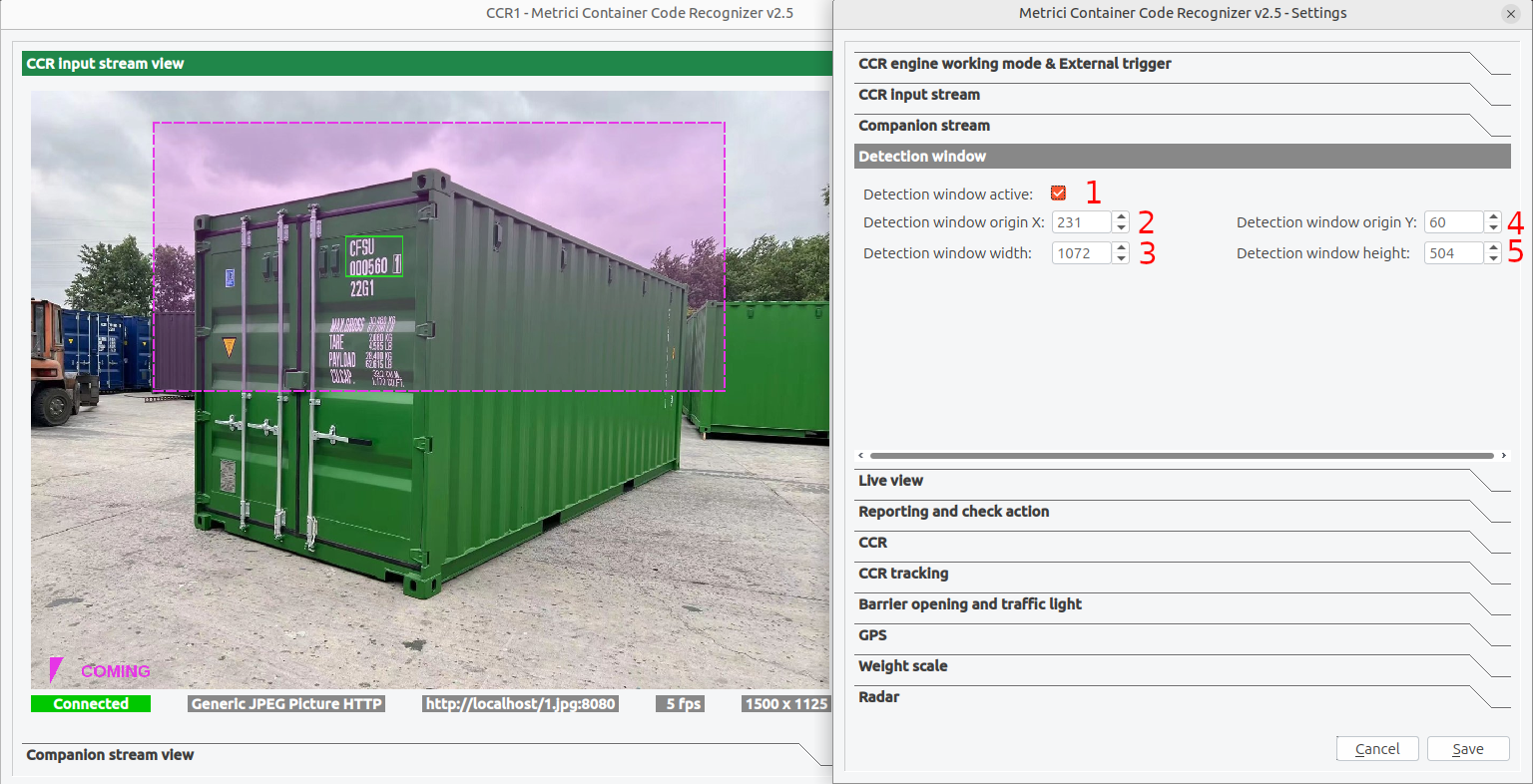
Activarea ferestrei de detecție
Pentru a activa fereastra de detecție bifați căsuța Detection window active — vezi Fig.4 Detection Window (1).
Poziționare și dimensionare
Fereastra este definită prin colțul din stânga sus și prin dimensiunile sale, toate exprimate în pixeli. Coordonatele se măsoară față de colțul din stânga sus al imaginii, care corespunde poziției (0, 0): valorile X cresc spre dreapta, iar valorile Y cresc în jos.
- Origin X: Poziția orizontală a colțului din stânga sus, măsurată de la marginea stângă — vezi Fig.4 Detection Window (2).
- Width: Lățimea ferestrei, în pixeli — vezi Fig.4 Detection Window (3).
- Origin Y: Poziția verticală a colțului din stânga sus, măsurată de la marginea superioară — vezi Fig.4 Detection Window (4).
- Height: Înălțimea ferestrei, în pixeli — vezi Fig.4 Detection Window (5).
Valorile reprezintă pixeli absoluți ai fluxului video, nu procente din cadru. Dacă schimbați camera sau rezoluția acesteia, fereastra de detecție trebuie reconfigurată.
Setări CCR
În meniul de setări CCR se reglează modul în care motorul acceptă și raportează un cod de container. Aici puteți evita detectarea codurilor duplicate, limita motorul la un singur cod pe cadru sau stabili dimensiunea în pixeli a codului de container. Această ultimă setare determină, în practică, distanța de lucru: cu cât containerul se află mai departe de cameră, cu atât codul ocupă mai puțini pixeli în imagine. Prin urmare, o valoare mai mică permite detecția la distanțe mai mari, iar o valoare mai mare ne ajută atunci cand containerele sunt aflate aproape de cameră.

Același cod CCR - ignorare (Same CCR delay)
Stabilește cât timp (în secunde) așteaptă motorul înainte de a raporta din nou același cod de container — vezi Fig.5 CCR (1). Astfel se împiedică generarea de evenimente repetate de către un singur container care rămâne în câmpul vizual.
Lungimea minimă și maximă CCR (pixeli)
Definesc lungimea minimă și maximă în pixeli pe care o poate avea un cod de container pentru a fi acceptat — vezi Fig.5 CCR (2). Folosiți lungimea în pixeli afișată sub Last detected CC în fereastra principală ca referință atunci când alegeți aceste valori — vezi Fig.1 CCR Main Interface.
- CCR min. length (pixels): Detecțiile mai scurte de această valoare sunt ignorate.
- CCR max. length (pixels): Detecțiile mai lungi de această valoare sunt ignorate.
Mod CCR unic (Single CCR mode)
Când este activat, motorul urmărește și raportează un singur cod de container la un moment dat — vezi Fig.5 CCR (3). Este alegerea potrivită pentru o poartă cu o singură bandă, unde containerele trec unul după altul. Dezactivați-l doar dacă în cadru pot apărea simultan mai multe containere și fiecare trebuie citit independent.
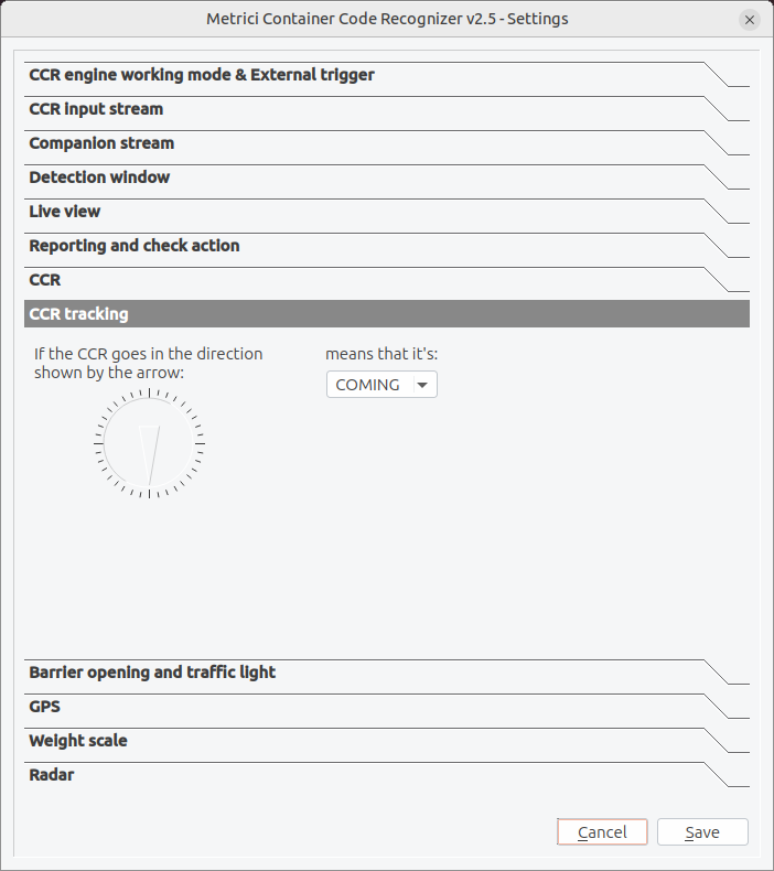
Urmărirea direcției
Urmărirea CCR indică sistemului ce sens de deplasare este considerat coming (intrare) și care este considerat leaving (ieșire). Sistemul observă modul în care containerul se deplasează prin cadru și etichetează evenimentul în consecință, astfel încât rapoartele arată dacă fiecare container a intrat sau a ieșit.
Setarea direcției
Cadranul afișează o săgeată de referință. Orientați săgeata în direcția în care containerele se deplasează fizic în imagine, apoi folosiți meniul derulant pentru a declara ce înseamnă acea mișcare — COMING sau LEAVING — vezi Fig.6 CCR Tracking. Direcția opusă este tratată automat ca cealaltă valoare.
Mod de lucru și declanșator extern
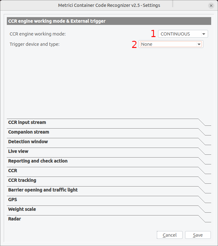
Aceste setări controlează când rulează motorul de recunoaștere. Îl puteți lăsa să analizeze continuu sau îl puteți face să pornească doar când un dispozitiv extern semnalează prezența unui container.
Modul de lucru al motorului CCR (CCR engine working mode)
Din CCR engine working mode — vezi Fig.7 CCR Engine Working Mode & External Trigger (1) — puteți alege între două opțiuni:
1. Mod continuu
- Descriere: Motorul analizează în mod constant fiecare imagine din fluxul de intrare.
- Consum de resurse: Ridicat — folosește mai mult CPU/GPU.
- Recomandat pentru: Porți unde containerele pot sosi în orice moment și nu este instalat un senzor de prezență.
2. Cu trigger — pornit prin declanșator
- Descriere: Recunoașterea începe când se primește un semnal de declanșare-trigger și continuă o durată stabilită.
- Economisește: Putere de procesare atunci când nu este prezent niciun container.
- Recomandat pentru: Porți cu buclă inductivă, radar sau alt senzor care se activează când un vehicul oprește la punctul de citire.
Trigger device and type
Când folosiți modul cu trigger, selectați sursa hardware sau software a declanșatorului din meniul Trigger device and type — vezi Fig.7 CCR Engine Working Mode & External Trigger (2). Setați-l la None pentru funcționare continuă, fără declanșator extern.
Tipuri de trigger
| Tip de trigger | Descriere |
|---|---|
| None | Fără trigger extern; funcționare continuă. |
| Barionet 50 I1-I4 | Intrările 1-4 ale controlerului Barionet 50 (dispozitiv I/O hardware). |
| Metrici Virtual | Trigger software din sistemul Metrici. |
Utilizarea Barionet
Barionet 50 este un controler I/O hardware care oferă intrări digitale. Conectați sursa trigger (senzor, buton, releu) la una dintre cele patru intrări:
- I1: Intrarea 1 (de obicei GPIO1)
- I2: Intrarea 2 (de obicei GPIO2)
- I3: Intrarea 3 (de obicei GPIO3)
- I4: Intrarea 4 (de obicei GPIO4)
Durata analizei după un trigger
În modul cu trigger, puteți seta și câte secunde continuă motorul să analizeze după fiecare semnal primit. Alegeți o valoare suficient de mare pentru ca un container să intre complet în câmpul vizual și să fie citit.
Metrici Virtual Trigger
Trigger Metrici Virtual permite unui motor Metrici să pornească un altul prin rețea. Este
folosit pentru verificare încrucișată — de exemplu, o citire LPR din fața unui camion declanșează o citire CCR a
containerului din spate, sau invers. Când selectați Metrici Virtual Trigger, acest motor așteaptă
semnalul pe un port UDP (de exemplu 3511).
Pentru a înlănțui două motoare, configurați mai întâi receptorul și notați portul acestuia, apoi copiați acel port în câmpul Send trigger at check action al motorului emițător (vezi Raportare și verificare acțiune). Cele două sunt astfel legate, iar prima detecție îl declanșează pe al doilea.
UNKNOWN, împreună cu un cadru fix pe care îl puteți examina pentru a verifica dacă a fost efectiv prezent un container.
Raportare și verificare acțiune
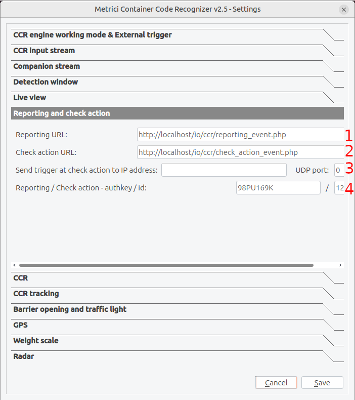
Această secțiune configurează modul în care sistemul trimite datele de recunoaștere către sisteme externe. Există două destinații înrudite, dar distincte: reporting (raportarea), care înregistrează fiecare cod recunoscut, și check action (verificarea acțiunii), care solicită unui sistem extern să valideze codul și să decidă ce urmează să se întâmple (de exemplu, dacă se deschide bariera).
Reporting URL
Introduceți URL-ul unde sistemul trebuie să trimită fiecare eveniment de recunoaștere — vezi Fig.8 Reporting & Check Action (1). Datele sunt trimise de obicei ca o cerere HTTP care include codul recunoscut și imaginea sa:
http://server_ip/io/ccr/reporting_event.phpCheck Action URL
Introduceți URL-ul care efectuează verificarea acțiunii — vezi Fig.8 Reporting & Check Action (2). Când un cod este recunoscut, sistemul contactează acest URL pentru ca o aplicație externă să poată valida codul față de o listă de acces sau o bază de date și să returneze răspunsul corespunzător:
http://server_ip/io/ccr/check_action_event.php127.0.0.1 ca adresă. Motorul reîncearcă trimiterea fiecărui eveniment de raportare până când serverul
confirmă primirea.
Send Trigger at Check Action
Opțional, când are loc o verificare a acțiunii, sistemul poate trimite și un trigger UDP către un dispozitiv din rețea — vezi Fig.8 Reporting & Check Action (3). Introduceți IP address și UDP port ale controlerului sau dispozitivului de automatizare care trebuie să primească semnalul.
Cheia de autentificare (authkey) și ID-ul
Authkey-ul și ID-ul autentifică sistemul pe serverul dumneavoastră Metrici, atât pentru raportare, cât și pentru verificarea acțiunii — vezi Fig.8 Reporting & Check Action (4). Aceste credențiale se obțin din interfața web Metrici, unde înregistrați camerele CCR într-o locație, și se completează aici pentru a iniția comunicarea dintre motorul de detecție și interfață. Pe baza acestei conexiuni se construiește baza de date și devin disponibile evenimentele, rapoartele și vizualizarea live.
Datele trimise în rapoarte
Fiecare eveniment de recunoaștere include:
- Marcajul de timp al evenimentului (first seen / last seen)
- Codul de container recunoscut (cod de proprietar, număr de serie și cifră de control)
- Codul de dimensiune/tip, când poate fi citit
- Sensul de deplasare (coming / leaving)
- Imaginea decupată a codului și, opțional, cadrul complet
- Greutatea, când este conectat un cântar
Vizualizare live
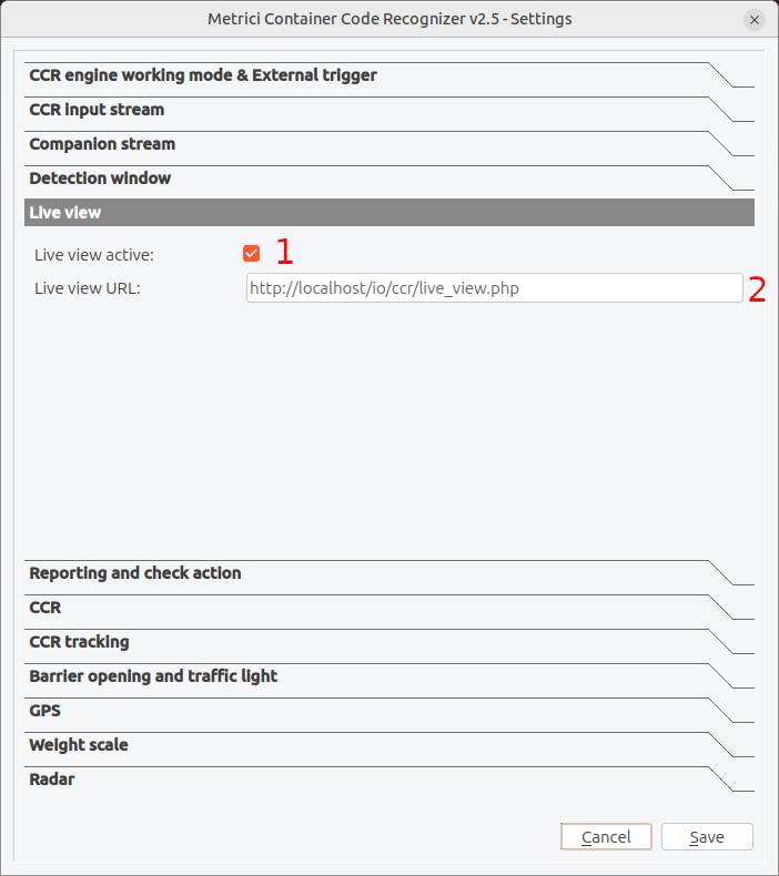
Funcția de vizualizare live permite vizualizarea de la distanță a ieșirii video a recognizerului printr-un browser web sau un client de streaming video.
Activarea vizualizării live
- Bifați Live view active în setări — vezi Fig.9 Live View (1).
- Introduceți URL-ul unde trebuie publicat fluxul video — vezi Fig.9 Live View (2).
- Salvați setările și reporniți aplicația.
Configurarea URL-ului pentru vizualizare live
Sistemul publică fluxul video procesat la URL-ul pe care îl furnizați. O configurație frecventă este:
http://server_ip/io/ccr/live_view.phpBarieră și semafor
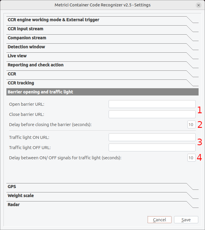
Această funcție permite sistemului să controleze echipamentele de acces de la poartă — o barieră și, opțional, un semafor — apelând URL-uri HTTP atunci când un container este recunoscut sau o verificare a acțiunii este aprobată. Este utilizată de obicei la punctele de intrare, porțile de terminal și incintele securizate.
Controlul barierei
- Open barrier URL: URL-ul HTTP care deschide bariera. De obicei este o comandă trimisă către un controler de barieră sau un sistem de automatizare — vezi Fig.10 Barrier Opening & Traffic Light (1).
- Close barrier URL: URL-ul HTTP care închide bariera. Sistemul poate închide bariera automat după ce containerul trece — vezi Fig.10 Barrier Opening & Traffic Light (2).
- Delay before closing the barrier (seconds): Cât timp rămâne bariera deschisă înainte de a fi închisă automat. Setați această valoare în funcție de fluxul obișnuit de trafic — vezi Fig.10 Barrier Opening & Traffic Light (3).
Controlul semaforului
- Traffic light ON URL: URL-ul HTTP care aprinde semaforul sau alt dispozitiv — vezi Fig.10 Barrier Opening & Traffic Light (4).
- Traffic light OFF URL: URL-ul HTTP care stinge semaforul — vezi Fig.10 Barrier Opening & Traffic Light (5).
- Delay between ON/OFF signals for traffic light (seconds): Timpul dintre semnalele ON și OFF, folosit pentru a temporiza ciclul semaforului — vezi Fig.10 Barrier Opening & Traffic Light (6).
GPS
Secțiunea GPS afișează starea unui receptor GPS atașat recognizerului și poziția pe care o raportează în prezent. Astfel, fiecare recunoaștere poate fi etichetată cu o locație geografică, ceea ce este util pentru unități de poartă mobile sau relocabile și pentru instalări care se integrează cu sisteme de management al flotei sau de dispecerat — vezi Fig.11 GPS.
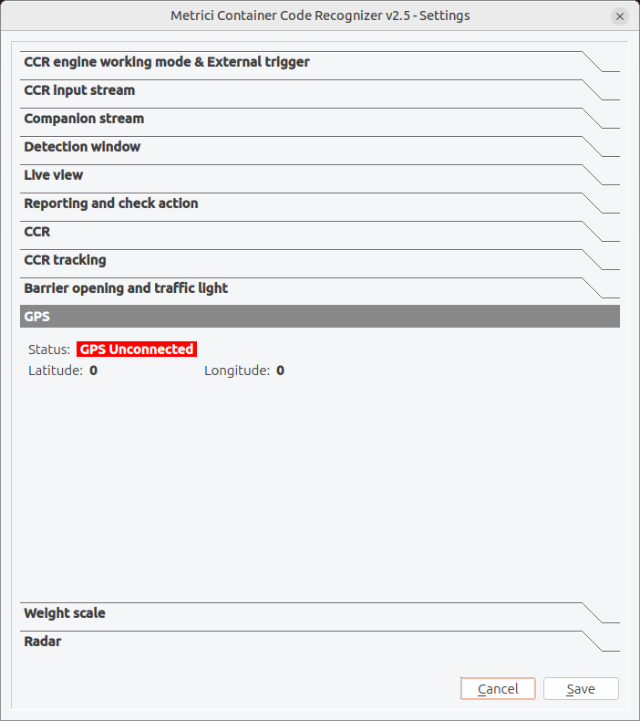
Panoul afișează trei câmpuri de stare, doar pentru citire:
- Status: Dacă un receptor GPS este detectat în prezent. GPS Unconnected (afișat cu roșu) înseamnă că niciun receptor nu este conectat; odată ce un dispozitiv este atașat și obține o poziție, starea se actualizează corespunzător.
- Latitude: Latitudinea curentă raportată de receptorul GPS. Afișează
0când niciun dispozitiv nu este conectat sau când nu este încă disponibilă o poziție. - Longitude: Longitudinea curentă raportată de receptorul GPS. Afișează, de asemenea,
0până la obținerea unei poziții.
Când este utilă funcția GPS
- Unități mobile sau relocabile care trebuie să își raporteze poziția.
- Instalări care se integrează cu sisteme de management al flotei sau de dispecerat.
- Locații unde fiecare recunoaștere trebuie etichetată cu o poziție geografică.
Cântar
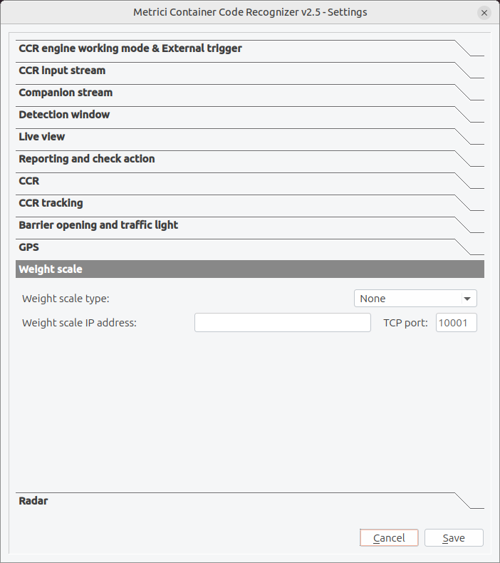
Funcția de cântar conectează motorul la un cântar, astfel încât fiecare container recunoscut să poată fi asociat cu o greutate măsurată. Greutatea este apoi inclusă în evenimentul de recunoaștere, oferind o singură înregistrare care leagă codul containerului de greutatea sa.
Configurare
- Weight scale type: Selectați din meniu modelul de cântar pe care îl conectați. Setați la None dacă nu se folosește niciun cântar — vezi Fig.12 Weight Scale.
- Weight scale IP address: Adresa de rețea a controlerului cântarului.
- TCP port: Portul folosit pentru comunicarea cu cântarul (implicit
10001).
Radar
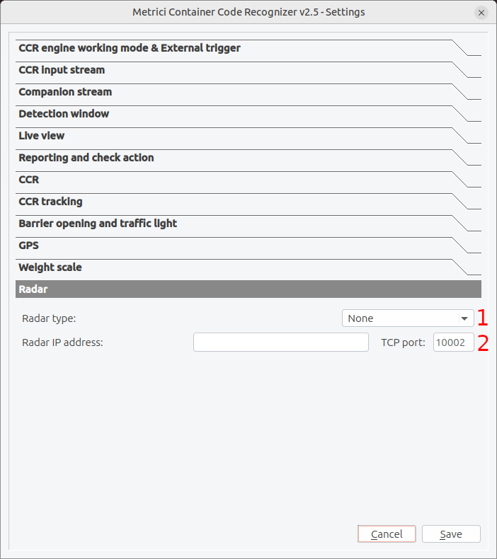
Un radar poate detecta prezența sau viteza unui vehicul și este folosit frecvent ca trigger care indică motorului când să înceapă citirea unui cod — vezi Mod de lucru și declanșator extern.
Configurare
- Radar type: Selectați modelul de radar -motoarele Metrici se conecteaza nativ la Observer Radar. Setați la None dacă nu se folosește niciun radar — vezi Fig.13 Radar (1).
- Radar IP address / TCP port: Adresa de rețea a unității radar și portul folosit pentru comunicarea cu aceasta (implicit
10002) — vezi Fig.13 Radar (2).
Depanare
Probleme de conexiune
| Problemă | Soluție |
|---|---|
| Camera nu se conectează | Verificați cablul de rețea, verificați adresa IP sau URL-ul instantaneului, confirmați că este alimentată camera. |
| Conexiunea se întrerupe frecvent | Măriți latența RTSP, verificați stabilitatea rețelei, reduceți calitatea video. |
| Imagine sau flux greșit | Verificați adresa fluxului sau calea instantaneului, verificați configurarea camerei pentru fluxul corect. |
| Autentificare eșuată | Confirmați numele de utilizator/parola, verificați caracterele speciale care necesită codare URL. |
Probleme de acuratețe a recunoașterii
| Problemă | Soluție |
|---|---|
| Codul nu este citit | Verificați că trece codul prin interiorul ferestrei de detecție; verificați că valorile CCR min./max. length permit dimensiunea în pixeli a codului. |
| Același cod raportat de mai multe ori | Măriți valoarea Same CCR delay; activați Single CCR mode pentru porțile cu o singură bandă. |
| Direcție greșită (coming/leaving) | Reverificați săgeata și meniul derulant din CCR tracking astfel încât să corespundă sensului real de deplasare. |
| Citiri false din alt text | Restrângeți fereastra de detecție astfel încât să acopere doar zona unde apare codul. |
Probleme de calitate a imaginii
| Problemă | Soluție |
|---|---|
| Caractere prea mici | Măriți sau repoziționați camera astfel încât codul să fie mai mare; setati corespunzător valoarea CCR minimum length. |
| Imagini neclare | Verificați focalizarea camerei; reduceți neclaritatea de mișcare cu o viteză mai mare a obturatorului. |
| Strălucire sau iluminare slabă | Adăugați sau repoziționați iluminarea; evitați lumina directă a soarelui sau reflexiile pe suprafața containerului. |
Probleme de performanță
| Problemă | Soluție |
|---|---|
| FPS scăzut | Folosiți fereastra de detecție pentru a limita zona procesată, reduceți limita FPS, reduceți rezoluția. |
| Utilizare ridicată a procesorului | Folosiți modul cu trigger cu un senzor sau radar, astfel încât motorul să ruleze doar când este prezent un container. |
| Consum de memorie în creștere | Reporniți periodic aplicația, reduceți dimensiunile bufferului video. |
Probleme cu bariera și semaforul
| Problemă | Soluție |
|---|---|
| Bariera nu răspunde | Verificați că URL-ul este corect, verificați conexiunea de rețea a controlerului barierei, testați manual URL-ul într-un browser. |
| Bariera se închide prea repede | Măriți întârzierea înainte de închiderea barierei. |
| Bariera se deschide neintenționat | Revizuiți logica de check action și configurarea trigger. |
| Semaforul rămâne blocat aprins sau stins | Confirmați că sunt setate atât URL-ul ON, cât și OFF, și verificați întârzierea dintre semnalele ON/OFF. |
Obținerea de ajutor
Dacă problemele persistă:
- Consultați jurnalele aplicației- logs pentru mesaje de eroare detaliate.
- Notați condițiile exacte în care apare problema.
- Contactați suportul tehnic cu:
- Versiunea aplicației
- Modelul și configurarea camerei
- Detalii despre sistemul de operare
- Mesaje de eroare sau fragmente de jurnal
Fișierul de configurare (fișier INI)
Metrici Container Code Recognizer stochează toate setările de configurare într-un fișier numit
[app_id].ini, unde [app_id] este identificatorul aplicației (de obicei un număr).
Acest fișier este creat automat în directorul aplicației la prima salvare a setărilor.
Înțelegerea fișierului INI
Fișierul INI este un format standard de fișier de configurare, organizat în perechi cheie-valoare. Puteți vizualiza sau edita acest fișier cu orice editor de text, dar este recomandat să folosiți fereastra Settings a aplicației pentru modificările de configurare, pentru a vă asigura că toate valorile sunt validate și salvate corect.
Locația fișierului INI
Fișierul INI este stocat în același director cu executabilul aplicației. Numele fișierului corespunde
ID-ului aplicației (de exemplu, 1.ini, 2.ini). Pot exista mai multe fișiere INI pentru
instanțe diferite ale aplicației.
Referință a valorilor de configurare
Tabelele următoare listează principalele valori de configurare stocate în fișierul INI, grupate pe secțiuni de setări, împreună cu valorile implicite tipice și o descriere a ceea ce controlează fiecare setare. Numele cheilor respectă convenția standard de denumire Metrici; verificați-le față de fișierul generat dacă îl editați manual.
Setări flux de intrare
| Nume setare | Valoare implicită | Descriere |
|---|---|---|
input_stream_type |
0 | Tipul fluxului de intrare (de ex. Generic JPEG Picture HTTP, RTSP, driver specific mărcii). |
input_stream_address |
http://localhost/1.jpg | Adresa de rețea, URL-ul instantaneului sau calea fișierului sursei video. |
input_stream_tcp_port |
8080 | Numărul portului folosit pentru conectarea la cameră. |
input_stream_username |
(empty) | Numele de utilizator pentru autentificarea camerei. |
input_stream_password |
(empty) | Parola pentru autentificarea camerei. |
input_stream_fps_limit |
0 | Numărul maxim de cadre pe secundă de procesat (0 = nelimitat). |
input_stream_resx |
(de la cameră) | Lățimea fluxului video de intrare, în pixeli. |
input_stream_resy |
(de la cameră) | Înălțimea fluxului video de intrare, în pixeli. |
input_stream_use_ssl |
0 | Folosește SSL/HTTPS pentru conexiunea fluxului de intrare (0 = nu, 1 = da). |
rtsp_stream_latency |
100 | Întârzierea de buffer RTSP, în milisecunde. |
rtsp_stream_protocols |
tcp | Protocolul de transport RTSP de încercat (tcp, udp sau ambele). |
Setări flux însoțitor
| Nume setare | Valoare implicită | Descriere |
|---|---|---|
companion_stream_type |
(undefined) | Tipul fluxului video însoțitor. |
companion_stream_address |
(empty) | Adresa de rețea sau calea fișierului sursei video însoțitoare. |
companion_stream_tcp_port |
80 | Numărul portului pentru conexiunea camerei însoțitoare. |
companion_stream_username |
(empty) | Numele de utilizator pentru autentificarea camerei însoțitoare. |
companion_stream_password |
(empty) | Parola pentru autentificarea camerei însoțitoare. |
companion_stream_resx |
640 | Lățimea fluxului video însoțitor, în pixeli. |
companion_stream_resy |
480 | Înălțimea fluxului video însoțitor, în pixeli. |
companion_stream_use_ssl |
0 | Folosește SSL/HTTPS pentru conexiunea fluxului însoțitor (0 = nu, 1 = da). |
Setări fereastră de detecție
| Nume setare | Valoare implicită | Descriere |
|---|---|---|
input_stream_window_active |
1 | Activează fereastra de detecție (0 = întregul cadru, 1 = regiune restrânsă). |
input_stream_window_origx |
231 | Poziția orizontală a colțului din stânga sus, în pixeli. |
input_stream_window_origy |
60 | Poziția verticală a colțului din stânga sus, în pixeli. |
input_stream_window_resx |
1072 | Lățimea ferestrei de detecție, în pixeli. |
input_stream_window_resy |
504 | Înălțimea ferestrei de detecție, în pixeli. |
Setări CCR și urmărire
| Nume setare | Valoare implicită | Descriere |
|---|---|---|
same_plate_delay |
3 | Secunde până când același cod de container poate fi raportat din nou. |
plate_min_length |
100 | Lungimea minimă acceptată a unui cod de container, în pixeli. |
plate_max_length |
1000 | Lungimea maximă acceptată a unui cod de container, în pixeli. |
single_plate_mode |
1 | Urmărește și raportează un singur cod la un moment dat (0 = dezactivat, 1 = activat). |
cars_direction |
0 | Sensul de deplasare (conform săgeții de urmărire) tratat ca coming; sensul opus este leaving. |
cars_event_type |
1 | Tipul de eveniment generat pentru fiecare recunoaștere. |
Setări motor și declanșator
| Nume setare | Valoare implicită | Descriere |
|---|---|---|
lpr_engine_working_mode |
0 | Modul motorului (0 = continuu, altă valoare = cu declanșare). |
external_trigger_type |
0 | Dispozitivul și tipul declanșatorului (0 = niciunul; alte valori selectează un declanșator hardware sau virtual). |
external_trigger_seconds |
1 | Câte secunde continuă motorul să analizeze după primirea unui declanșator. |
Setări raportare și verificare acțiune
| Nume setare | Valoare implicită | Descriere |
|---|---|---|
reporting_url |
http://localhost/io/ccr/reporting_event.php | URL-ul unde sunt trimise evenimentele de recunoaștere. |
check_action_url |
http://localhost/io/ccr/check_action_event.php | URL-ul contactat pentru a valida un cod și a decide acțiunea. |
check_action_send_trigger_address |
(empty) | Adresa IP care primește un trigger UDP la verificarea acțiunii. |
check_action_send_trigger_udp_port |
0 | Portul UDP pentru declanșatorul de verificare a acțiunii (0 = dezactivat). |
reporting_check_action_authkey |
(empty) | Cheie de securitate pentru autentificarea cererilor de raportare și de verificare a acțiunii. |
reporting_check_action_id |
0 | Identificatorul acestei instanțe de recognizer în raportare. |
Setări vizualizare live
| Nume setare | Valoare implicită | Descriere |
|---|---|---|
live_view_active |
1 | Activează streamingul de vizualizare live (0 = dezactivat, 1 = activat). |
live_view_url |
http://localhost/io/ccr/live_view.php | URL-ul unde este publicat fluxul video procesat. |
Setări barieră, semafor, cântar și radar
Motorul comandă două ieșiri HTTP: o barieră principală și o a doua ieșire (cheile *_barrier2_*). În interfața CCR, a doua ieșire este prezentată drept controlul ON/OFF al semaforului — nu există chei separate traffic_light_*.
| Nume setare | Valoare implicită | Descriere |
|---|---|---|
open_barrier_url |
(empty) | URL-ul HTTP care deschide bariera. |
close_barrier_url |
(empty) | URL-ul HTTP care închide bariera. |
open_close_barrier_delay |
10 | Secunde cât rămâne bariera deschisă înainte de închiderea automată. |
open_barrier2_url |
(empty) | URL HTTP pentru a doua ieșire — deschide a doua barieră sau trimite semnalul ON al semaforului. |
close_barrier2_url |
(empty) | URL HTTP pentru a doua ieșire — închide a doua barieră sau trimite semnalul OFF al semaforului. |
open_close_barrier2_delay |
10 | Întârzierea pentru a doua ieșire, în secunde. |
weight_scale_type |
0 | Tipul cântarului conectat (0 = niciunul). |
weight_scale_address |
(empty) | Adresa IP a controlerului cântarului. |
weight_scale_tcp_port |
10001 | Portul TCP pentru comunicarea cu cântarul. |
radar_type |
0 | Tipul radarului conectat (0 = niciunul). |
radar_address |
(empty) | Adresa IP a unității radar. |
radar_tcp_port |
10002 | Portul TCP pentru comunicarea cu radarul. |
Exemplu de fișier INI
Mai jos este un exemplu de cum arată un fișier INI tipic, cu valori de configurare de exemplu:
[General]
cars_direction=0
cars_event_type=1
check_action_send_trigger_address=
check_action_send_trigger_udp_port=0
check_action_url=http://localhost/io/ccr/check_action_event.php
close_barrier2_url=
close_barrier_url=
companion_stream_address=
companion_stream_password=
companion_stream_resx=640
companion_stream_resy=480
companion_stream_tcp_port=80
companion_stream_type=0
companion_stream_use_ssl=0
companion_stream_username=
external_trigger_seconds=1
external_trigger_type=0
input_stream_address=http://localhost/1.jpg
input_stream_fps_limit=0
input_stream_password=
input_stream_resx=4284
input_stream_resy=5712
input_stream_tcp_port=8080
input_stream_type=33
input_stream_use_ssl=0
input_stream_username=
input_stream_window_active=0
input_stream_window_origx=668
input_stream_window_origy=1188
input_stream_window_resx=668
input_stream_window_resy=1188
live_view_active=1
live_view_url=http://localhost/io/ccr/live_view.php
lpr_engine_working_mode=0
open_barrier2_url=
open_barrier_url=
open_close_barrier2_delay=10
open_close_barrier_delay=10
plate_max_length=1000
plate_min_length=100
radar_address=
radar_tcp_port=10002
radar_type=0
reporting_check_action_authkey=
reporting_check_action_id=0
reporting_url=http://localhost/io/ccr/reporting_event.php
rtsp_stream_latency=100
rtsp_stream_protocols=tcp
same_plate_delay=3
single_plate_mode=1
weight_scale_address=
weight_scale_tcp_port=10001
weight_scale_type=0Fișiere de configurare multiple
Puteți crea mai multe fișiere INI pentru configurări diferite prin schimbarea ID-ului aplicației. Acest lucru este util pentru:
- Configurări diferite de camere la porți sau locații diferite.
- Testarea unor setări noi fără a afecta configurarea de producție.
- Comutarea între scenarii de recunoaștere diferite.
Pur și simplu copiați fișierul INI cu un alt nume și configurați aplicația să folosească acel fișier.
Glosar
Anatomia unui cod de container (ISO 6346)
Un cod standard de identificare a containerului este format din patru părți. Folosind exemplul
CFSU 000560 [1] prezentat în acest manual:
| Parte | Exemplu | Semnificație |
|---|---|---|
| Cod de proprietar | CFS | Trei litere care identifică proprietarul înregistrat sau operatorul principal al containerului. |
| Identificator al categoriei de echipament | U | O literă pentru tipul de echipament: U = container de marfă, J = echipament detașabil, Z = remorcă/șasiu. |
| Număr de serie | 000560 | Șase cifre atribuite de proprietar pentru a identifica în mod unic unitatea. |
| Cifră de control | [1] | O singură cifră, calculată din caracterele precedente, folosită pentru a valida că a fost citit corect codul. |
Codul este afișat de obicei împreună cu un cod de dimensiune/tip de patru caractere (de exemplu
22G1), care codifică dimensiunile și tipul constructiv al containerului.
Termeni
- Container Code (CC)
- Codul de identificare ISO 6346 marcat pe un container, citit de recognizer.
- Check Digit
- Ultima cifră a unui cod de container, folosită pentru a confirma că restul codului a fost citit corect.
- Check Action
- O cerere către un sistem extern de a valida un cod recunoscut și de a decide ce urmează, de exemplu deschiderea unei bariere.
- Detection Window
- Regiunea dreptunghiulară a imaginii în care motorul caută un cod de container.
- FPS
- Frames Per Second (cadre pe secundă) — o măsură a numărului de imagini procesate pe secundă.
- ISO 6346
- Standardul internațional care definește codificarea, identificarea și marcarea containerelor de transport.
- Owner Code
- Prefixul de trei litere al unui cod de container care identifică proprietarul înregistrat.
- RTSP
- Real Time Streaming Protocol — un protocol standard pentru transmiterea video prin rețele.
- Size/Type Code
- Un cod de patru caractere (de ex. 22G1) care descrie dimensiunile și tipul unui container.
- Trigger
- Un semnal (hardware sau software) care determină sistemul să înceapă recunoașterea sau să execute o acțiune.