Metrici Container Code Recognizer
User Manual for End Users and System Administrators

Table of Contents
- Getting Started
- Main Window Overview
- Input Stream Configuration
- Companion Stream
- Detection Window
- CCR Recognition Settings
- CCR Tracking
- Engine Working Mode & External Trigger
- Reporting & Check Action
- Live View
- Barrier Opening & Traffic Light
- GPS
- Weight Scale
- Radar
- Troubleshooting
Getting Started
What This System Does
The Metrici Container Code Recognizer (CCR) is an AI video analysis application that automatically detects and reads the identification codes marked on intermodal shipping containers. It connects to your camera, processes the image in real time, and reports each recognized container code together with a timestamp and other data. It can also validate the code, forward it to external systems, and trigger automated responses such as opening a barrier or switching a traffic light.
Container codes follow the international ISO 6346 standard. A complete code is made up of
an owner code, an equipment category identifier, a six-digit serial number and a check digit — for example
CFSU 000560 [1] — usually shown together with the size/type code (for example 22G1).
The system reads these characters, validates the check digit, and stores the result. See
Glossary for a full
breakdown of the code structure.
The system is used across the container-handling industry:
- Port and terminal gates: Identify containers entering or leaving on trucks at the gate.
- Container depots and yards: Keep an accurate inventory of stored equipment.
- Rail terminals: Read codes on containers moving by rail or on chassis.
- Weighbridges: Pair the recognized code with a measured weight for each container.
- Access control: Grant or deny passage based on a recognized, validated code.
System Requirements
- Camera: IP camera or image/video source positioned to capture the container code clearly.
- Network: Stable connection for camera access (if using IP cameras).
- License Key: Valid key for software activation.
Starting the Application
The application automatically starts every time the server is on. If not, launch the application from the command line. The system will initialize and connect to your configured video source. If this is your first time running the application, you will see a settings window where you can configure all your options.
Main Window Overview
The main window displays your video feed on the left and the recognition results on the right. Understanding each section will help you operate the system efficiently.
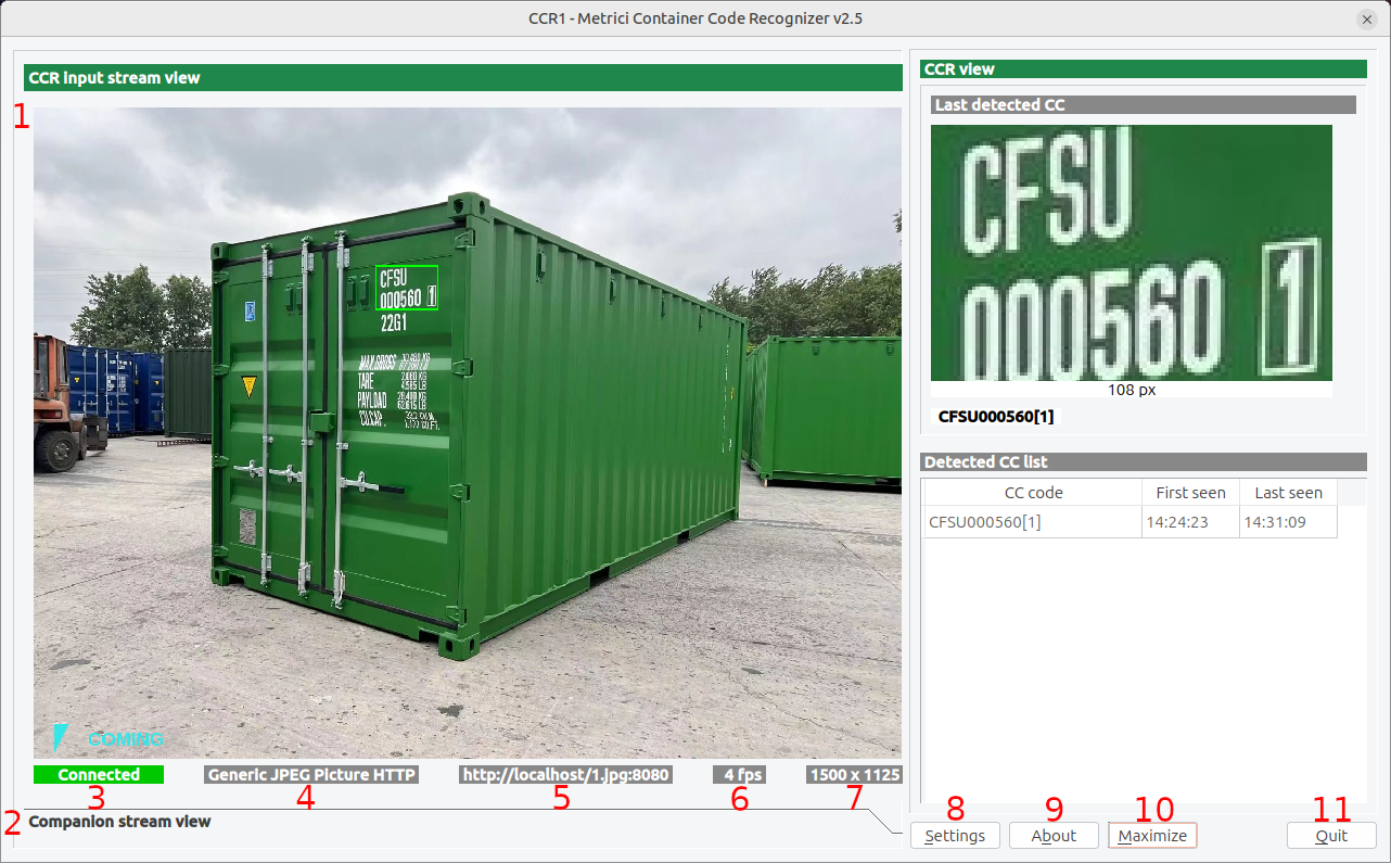
Video Display Area
The left area shows the processed video feed with:
- CCR Input Stream View: Your primary video source — see Fig.1 CCR Main Interface (1).
- Companion Stream View: (Optional) Secondary video source for an alternative view — see Fig.1 CCR Main Interface (2).
Status Bar
Below the video, you will see status information:
- Connection Status: Shows if the camera is connected, disconnected, or connecting — see Fig.1 CCR Main Interface (3).
- Stream Type: Type of video source (Generic JPEG Picture HTTP, RTSP, etc.) — see Fig.1 CCR Main Interface (4).
- Stream Address: IP address or URL of the camera — see Fig.1 CCR Main Interface (5).
- FPS: Frames per second being processed — see Fig.1 CCR Main Interface (6).
- Resolution: Video resolution (width × height) — see Fig.1 CCR Main Interface (7).
Recognition Results (CCR View)
The right area shows what the engine has read:
- Last detected CC: A cropped image of the most recently recognized container code, the
pixel length of that code, and the decoded text (for example
CFSU000560[1]). Use this panel to confirm the engine is reading the code correctly. - Detected CC list: A table of recognized codes with the columns CC code, First seen and Last seen. Each row records when a container code was first read and when it was last observed.
Control Buttons
- Settings: Opens the configuration window to adjust all settings — see Fig.1 CCR Main Interface (8).
- About: Shows version and license information — see Fig.1 CCR Main Interface (9).
- Maximize: Toggles between full-screen and windowed mode — see Fig.1 CCR Main Interface (10).
- Quit: Closes the application — see Fig.1 CCR Main Interface (11).
Input Stream Configuration
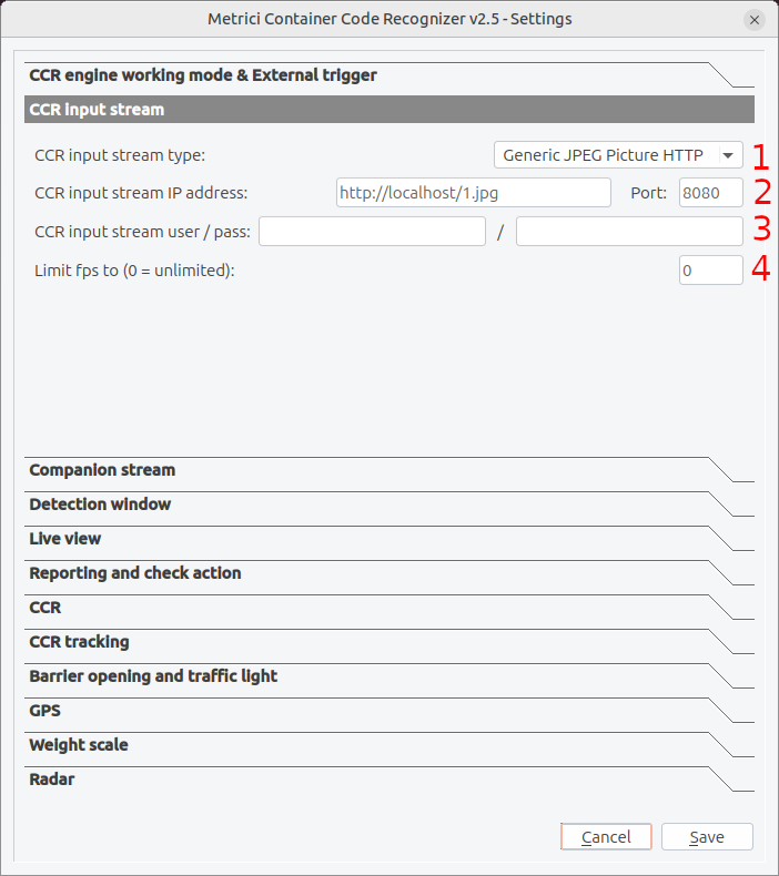
The first and most important setup is configuring your video source. Click the Settings button to open the configuration window — see Fig.1 CCR Main Interface (8) — then open the CCR input stream section.
Input Stream Type
Select how the camera delivers its image from the dropdown — see Fig.2 CCR Input Stream (1). Container gates very often use a fixed camera that publishes a still JPEG snapshot over HTTP, which is why Generic JPEG Picture HTTP is a common choice. The system also includes optimized drivers for many popular camera brands:
- ACTi: supported codecs: MJPEG, H264; standard protocols (HTTP, RTSP)
- Android: supported codecs: MJPEG; standard protocols (HTTP)
- Arecont Vision: supported codecs: MJPEG; standard protocols (HTTP)
- Axis: supported codecs: MJPEG, H264; standard protocols (HTTP, RTSP)
- Bosch: supported codecs: MJPEG, H264; standard protocols (RTSP)
- Dahua: supported codecs: MJPEG; standard protocols (HTTP)
- Divotec: supported codecs: MJPEG, H264; standard protocols (HTTP, RTSP)
- Hikvision: supported codecs: MJPEG, H264; standard protocols (HTTP, RTSP)
- Mobotix: supported codecs: MJPEG, MxPEG; standard protocols (HTTP)
- Novus: supported codecs: MJPEG, H264; standard protocols (HTTP, RTSP)
- Pelco: supported codecs: MJPEG; standard protocols (RTSP)
- Roseek: RAW
- Samsung: supported codecs: MJPEG, H264; standard protocols (HTTP, RTSP)
- Sony: supported codecs: MJPEG, H264; standard protocols (HTTP, RTSP)
- Uniview: supported codecs: H264; standard protocols (RTSP)
- VLC: supported codecs: MJPEG; standard protocols (HTTP)
- Vivotek: supported codecs: MJPEG; standard protocols (HTTP)
- Generic: supported codecs: MJPEG, H264; standard protocols (HTTP, RTSP)
http://localhost/1.jpg). For a video camera, RTSP H.264 is recommended for most installations
as it provides the best balance of image quality and network efficiency.
Step-by-Step Setup:
- Click the Settings button on the main interface — see Fig.1 CCR Main Interface (8).
- Select "CCR input stream" from the settings categories — see Fig.2 CCR Input Stream.
- Stream Type: Select your camera's protocol from the dropdown list — see Fig.2 CCR Input Stream (1).
- IP Address: Enter the camera's IP address, or the full snapshot URL for a JPEG source — see Fig.2 CCR Input Stream (2).
- Port: Enter the port (default HTTP is 80) — other protocols use different ports — see Fig.2 CCR Input Stream (2).
- Username/Password: Enter credentials if your camera is password protected — see Fig.2 CCR Input Stream (3).
- Limit FPS: Set to 0 for unlimited, or specify a maximum frame rate — see Fig.2 CCR Input Stream (4). Because containers move slowly through a gate, a high frame rate is not required; limiting FPS reduces load without affecting accuracy.
RTSP Stream Latency
This setting can be changed in the .ini file as rtsp_stream_latency. When an RTSP camera is used, set the buffering delay. Higher values (500-2000ms) provide smoother video but
increase the delay between actual events and system response. For real-time recognition, use lower values
(100-300ms). By default the settings are set to (100-300ms).
RTSP Protocol Selection
This setting can be changed in the .ini file as rtsp_stream_protocols. Choose which RTSP protocols to attempt. Using UDP is faster but may have issues through firewalls. TCP is
more reliable but slightly slower. You can enable both to let the system try UDP first, then fall back to TCP
if needed. The default RTSP protocol that is set is TCP.
The settings are done in the .ini file.
Companion Stream
The companion stream feature allows you to connect a second camera that can provide an additional viewpoint for verification — for example, a wide shot of the truck and container while the main camera reads the code.
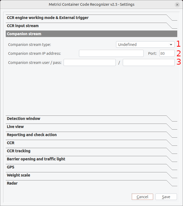
Use the Companion Stream tab and fill in the data only if a second camera (different from the CCR one) is available for this purpose. Otherwise leave it blank.
Configuration Options
The companion stream uses the same configuration options as the main stream: type, address, authentication and port. Configure it independently based on your second camera's capabilities — see the fields for Companion stream type Fig.3 Companion Stream (1), IP address / Port Fig.3 Companion Stream (2) and user / pass Fig.3 Companion Stream (3).
When to Use Companion Stream
- Multiple angle capture: The main camera reads the code while the companion camera captures the full truck and container for the record.
Detection Window
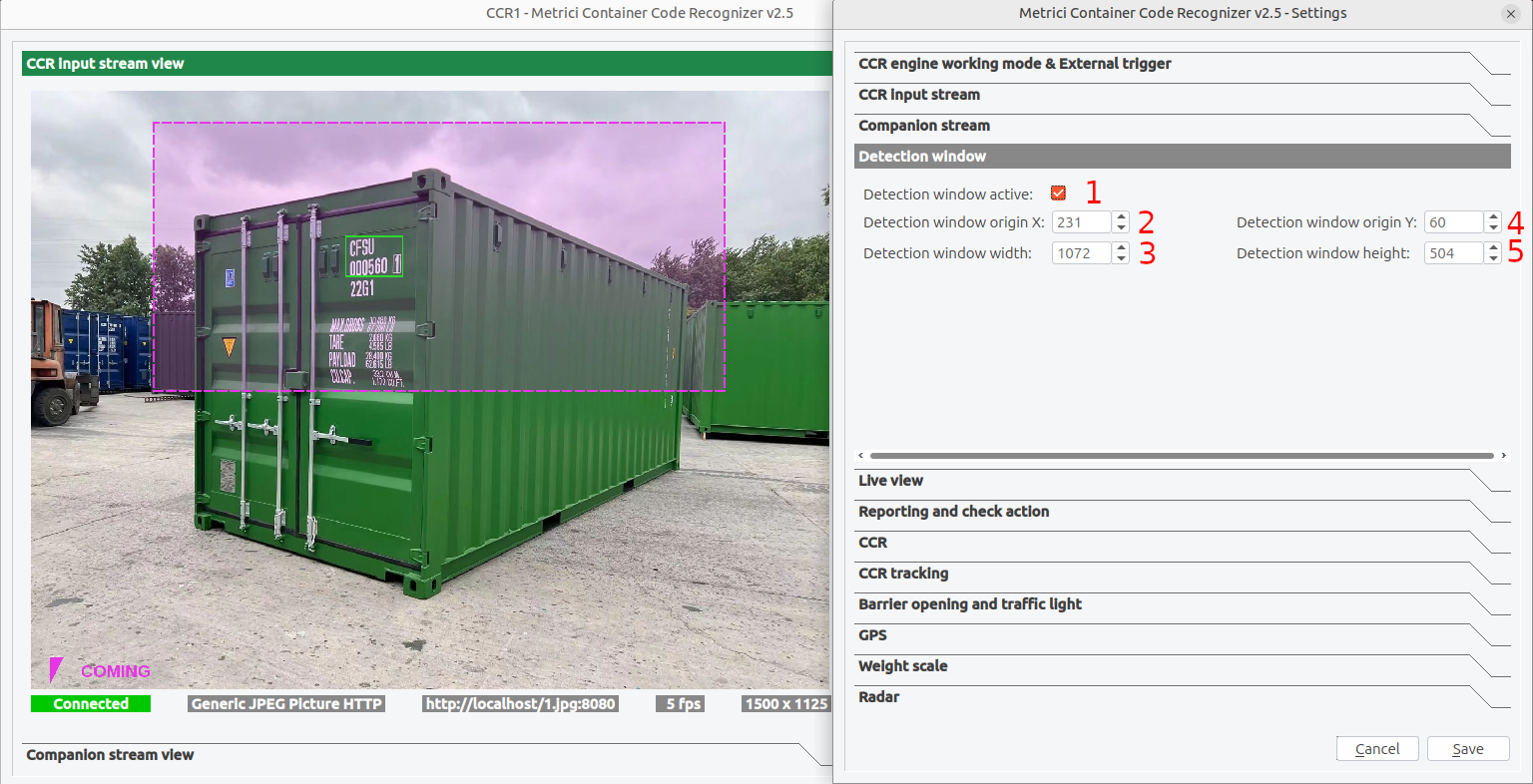
The detection window defines the rectangular area of the image where the engine searches for a container code. Restricting recognition to the part of the frame where codes actually appear speeds up processing. On the live view it is drawn as a dashed rectangle over the image — see Fig.4 Detection Window.
Enabling the Detection Window
Tick Detection window active to switch it on — see Fig.4 Detection Window (1). When it is disabled, the engine analyzes the whole frame.
Positioning and Sizing
The window is defined by its top-left corner and its size, all measured in pixels. Coordinates are measured from the top-left corner of the image, which corresponds to position (0, 0): X values increase to the right, while Y values increase downward.
- Origin X: Horizontal position of the top-left corner, measured from the left edge — see Fig.4 Detection Window (2).
- Width: Width of the window in pixels — see Fig.4 Detection Window (3).
- Origin Y: Vertical position of the top-left corner, measured from the top edge — see Fig.4 Detection Window (4).
- Height: Height of the window in pixels — see Fig.4 Detection Window (5).
These values are absolute pixels of the video stream, not percentages of the frame. If you change the camera or its resolution, the detection window must be configured again.
CCR Recognition Settings
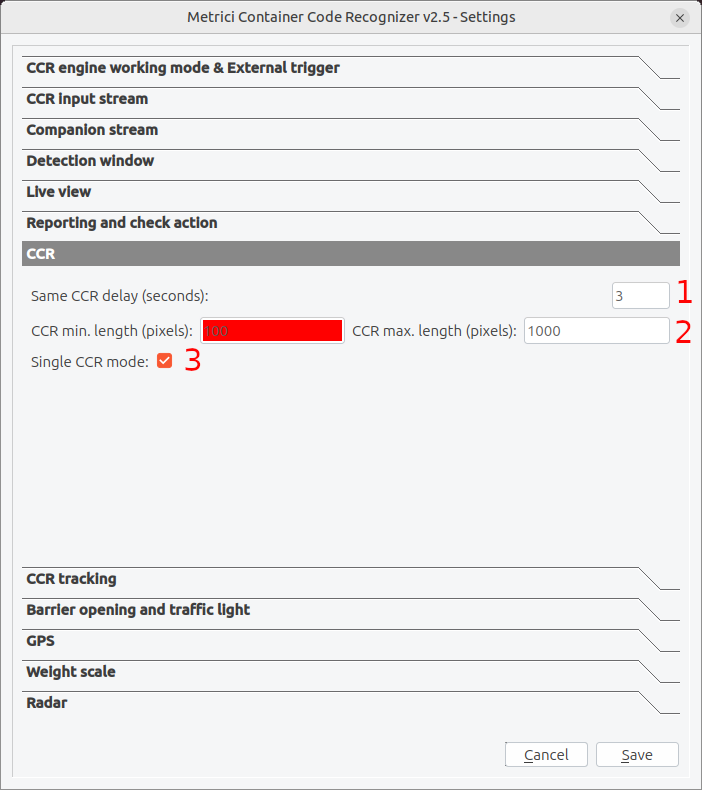
The CCR settings menu controls how the engine accepts and reports a container code. Here you can prevent duplicate code detection, restrict the engine to a single code per frame, or set the size of the container code in pixels. This last setting determines, in practice, the working distance: the farther the container is from the camera, the fewer pixels the code occupies in the image. Consequently, a smaller value allows detection at greater distances, while a larger value helps when the containers are close to the camera.
Same CCR Delay
Sets how long (in seconds) the engine waits before it will report the same container code again — see Fig.5 CCR (1). This prevents a single container that stays in view from generating repeated events. Increase it if the same code is being logged multiple times.
CCR Minimum and Maximum Length (pixels)
Define the smallest and largest pixel length a container code may have to be accepted — see Fig.5 CCR (2). A code narrower than the minimum is usually too far away or is noise; a code wider than the maximum is usually a false detection. Use the pixel length shown under Last detected CC in the main window as a reference when choosing these values — see Fig.1 CCR Main Interface.
- CCR min. length (pixels): Detections shorter than this are ignored.
- CCR max. length (pixels): Detections longer than this are ignored.
Single CCR Mode
When enabled, the engine tracks and reports only one container code at a time — see Fig.5 CCR (3). This is the right choice for a single-lane gate where containers pass one after another. Disable it only if more than one container can appear in the frame at once and each must be read independently.
CCR Tracking
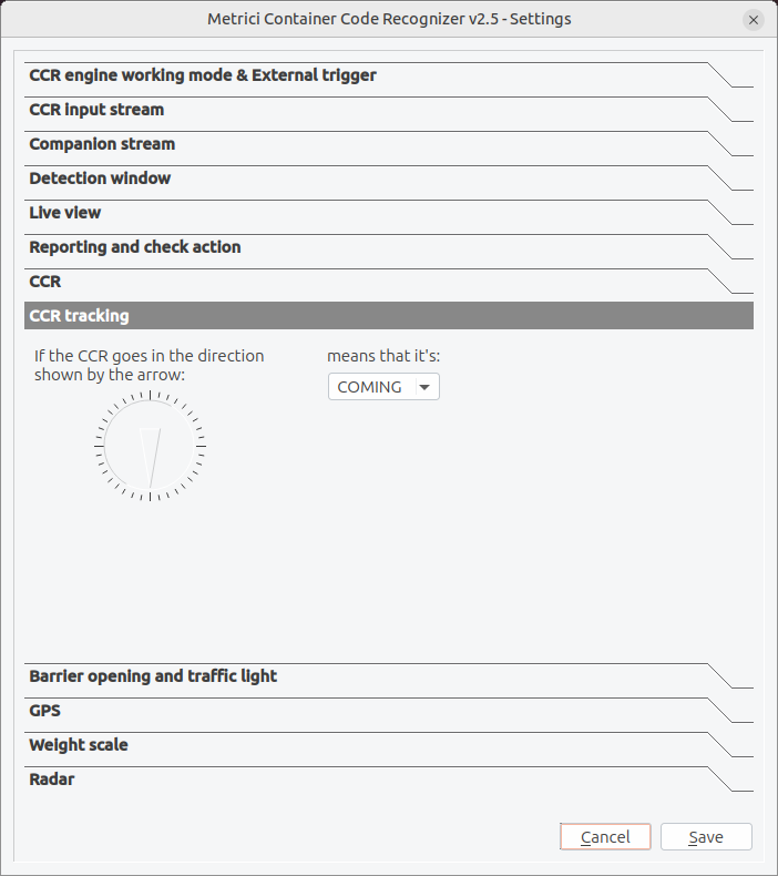
CCR tracking tells the system what direction of travel counts as coming (entering) and what counts as leaving (exiting). The system watches how the container moves through the frame and labels the event accordingly, so your reports show whether each container entered or left.
Setting the Direction
The dial shows a reference arrow. Point the arrow in the direction that containers physically move on your image, then use the dropdown to declare what that movement means — COMING or LEAVING — see Fig.6 CCR Tracking. The opposite direction is automatically treated as the other value.
Engine Working Mode & External Trigger
These settings control when the recognition engine runs. You can let it analyze continuously, or have it start only when an external device signals that a container is present.
CCR Engine Working Mode
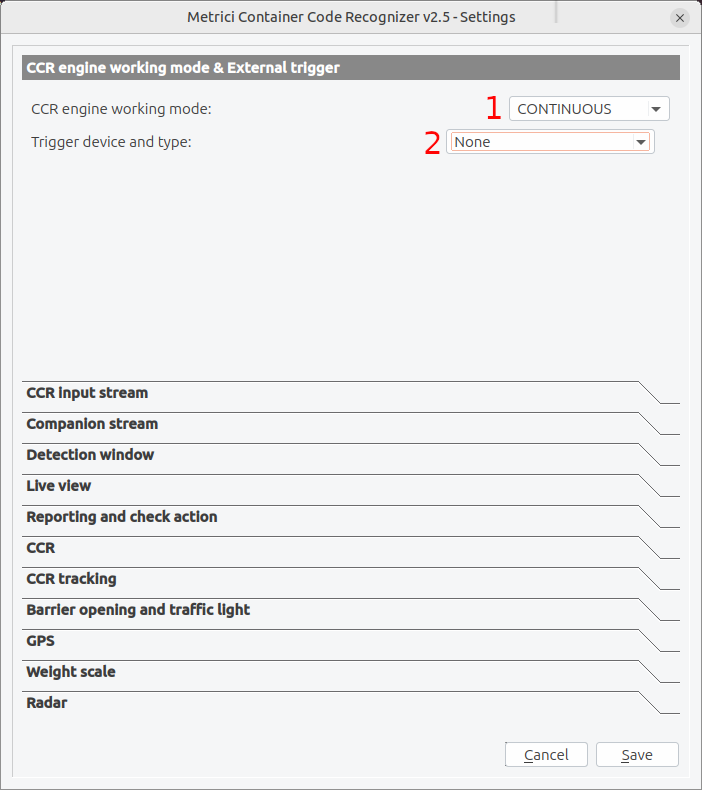
From CCR engine working mode — see Fig.7 CCR Engine Working Mode & External Trigger (1) — you can choose between two options:
1. Continuous Mode
- Description: The engine constantly analyzes every image from the input stream.
- Resource usage: High — uses more CPU/GPU.
- Best for: Gates where containers can arrive at any moment and no presence sensor is installed.
2. Triggered — Started by Trigger
- Description: Recognition starts when a trigger signal is received and continues for a set duration.
- Saves: Processing power when no container is present.
- Best for: Gates with an inductive loop, radar, or other sensor that fires when a vehicle stops at the reading point.
Trigger Device and Type
When you use triggered mode, select the hardware or software source of the trigger from the Trigger device and type dropdown — see Fig.7 CCR Engine Working Mode & External Trigger (2). Set it to None for continuous operation with no external trigger.
Trigger Types
| Trigger Type | Description |
|---|---|
| None | No external trigger; continuous operation. |
| Barionet 50 I1-I4 | Barionet 50 controller inputs 1-4 (hardware I/O device). |
| Metrici Virtual | Software trigger from the Metrici system. |
Using Barionet Triggers
The Barionet 50 is a hardware I/O controller that provides digital inputs. Connect your trigger source (sensor, button, relay) to one of the four inputs:
- I1: Input 1 (typically GPIO1)
- I2: Input 2 (typically GPIO2)
- I3: Input 3 (typically GPIO3)
- I4: Input 4 (typically GPIO4)
Analysis Duration After a Trigger
In triggered mode you can also set how many seconds the engine keeps analyzing after each trigger is received. Choose a value long enough for the container to come fully into view and be read.
Metrici Virtual Trigger
The Metrici Virtual trigger lets one Metrici engine start another over the network. This is
used for cross-checking — for example, an LPR reading in front of a truck triggers a CCR reading of the
container at the back, or the other way around. When you select Metrici Virtual Trigger, this engine listens
for the signal on a UDP port (for example 3511).
To chain two engines, set up the receiver first and note its port, then copy that port into the sender engine's Send trigger at check action field (see Reporting & Check Action). The two are then linked, so the first detection triggers the second.
UNKNOWN, together with a still frame you can review to check whether a container was actually
present.
Reporting & Check Action
This section configures how the system sends recognition data to external systems. There are two related but distinct destinations: reporting, which logs every recognized code, and check action, which asks an external system to validate the code and decide what should happen next (for example, whether to open the barrier).
Reporting URL
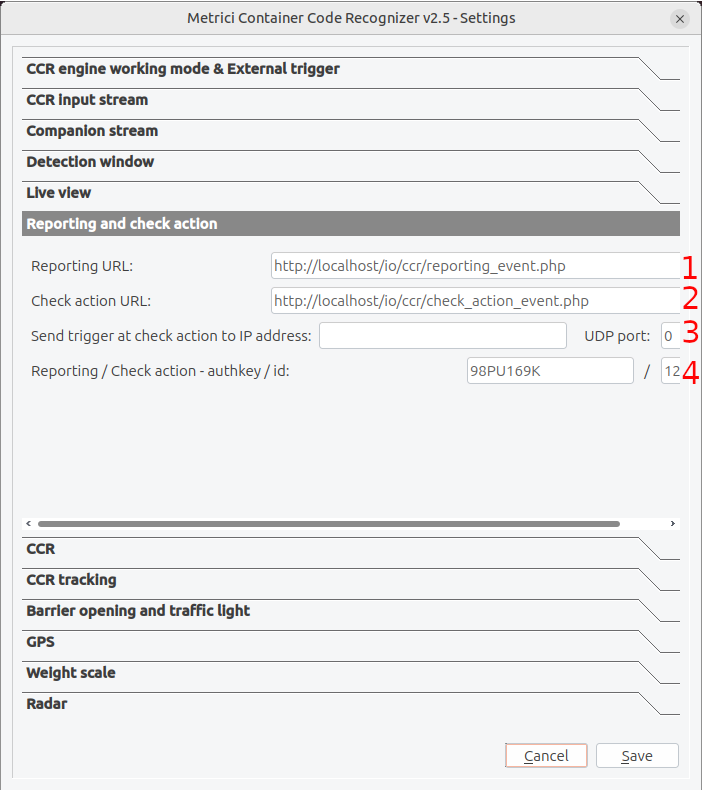
Enter the URL where the system should send each recognition event — see Fig.8 Reporting & Check Action (1). Data is typically sent as an HTTP request that includes the recognized code and its image:
http://server_ip/io/ccr/reporting_event.phpCheck Action URL
Enter the URL that performs the check action — see Fig.8 Reporting & Check Action (2). When a code is recognized, the system contacts this URL so an external application or Metrici logic can validate the code against an access list or database and return the appropriate response:
http://server_ip/io/ccr/check_action_event.php127.0.0.1 as the address. The engine keeps retrying each reporting event until the server
confirms it was received.
Send Trigger at Check Action
Optionally, when a check action occurs the system can also send a UDP trigger to a device on the network —
see Fig.8 Reporting & Check Action (3).
Enter the target IP address and UDP port of the controller or automation
device that should receive the signal. Leave the port at 0 to disable this.
Authentication Key and ID
The authkey and ID authenticate the system with your Metrici server for both reporting and check action — see Fig.8 Reporting & Check Action (4). These credentials are obtained from the Metrici web interface, where you register your CCR cameras into a location. This is how the detection egine comunicates with the Interface and builds database.
Data Sent in Reports
Each recognition event includes:
- Timestamp of the event (first seen / last seen)
- The recognized container code (owner code, serial number and check digit)
- Size/type code, when readable
- Direction of travel (coming / leaving)
- The cropped code image and, optionally, the full frame
- Weight, when a weight scale is connected
Live View
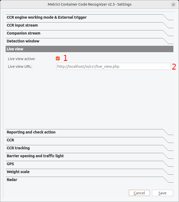
The live view feature allows remote viewing of the recognizer's video output through a web browser or a video streaming client.
Enabling Live View
- Tick Live view active in the settings — see Fig.9 Live View (1).
- Enter the URL where the video stream should be published — see Fig.9 Live View (2).
- Save the settings and restart the application.
Live View URL Configuration
The system publishes the processed video feed at the URL you provide. A common configuration is:
http://server_ip/io/ccr/live_view.phpBarrier Opening & Traffic Light
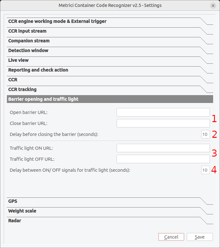
This feature lets the system control access equipment at the gate — a barrier and, optionally, a traffic light — by calling HTTP URLs when a container is recognized or a check action is granted. It is typically used at entry points, terminal gates, and secure facilities.
Barrier Control
- Open barrier URL: The HTTP URL that opens the barrier. This is usually a command sent to a barrier controller or automation system — see Fig.10 Barrier Opening & Traffic Light (1).
- Close barrier URL: The HTTP URL that closes the barrier. The system can close the barrier automatically after the container passes — see Fig.10 Barrier Opening & Traffic Light (2).
- Delay before closing the barrier (seconds): How long the barrier stays open before it is automatically closed. Set this based on your typical traffic flow — see Fig.10 Barrier Opening & Traffic Light (3).
Traffic Light Control
- Traffic light ON URL: The HTTP URL that switches the traffic light on or other hardware system — see Fig.10 Barrier Opening & Traffic Light (4).
- Traffic light OFF URL: The HTTP URL that switches the traffic light off — see Fig.10 Barrier Opening & Traffic Light (5).
- Delay between ON/OFF signals for traffic light (seconds): The time between the ON and OFF signals, used to time the light cycle — see Fig.10 Barrier Opening & Traffic Light (6).
GPS
The GPS section shows the status of a GPS receiver attached to the recognizer and the position it currently reports. This allows each recognition to be tagged with a geographic location, which is useful for mobile or relocatable gate units and for installations that integrate with fleet management or dispatch systems — see Fig.11 GPS.
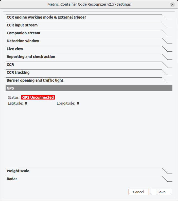
The panel displays three read-only status fields:
- Status: Whether a GPS receiver is currently detected. GPS Unconnected (shown in red) means no receiver is connected; once a device is attached and obtains a fix, the status updates accordingly.
- Latitude: The current latitude reported by the GPS receiver. It reads
0when no device is connected or no position fix is available yet. - Longitude: The current longitude reported by the GPS receiver. It also reads
0until a fix is obtained.
When GPS Is Useful
- Mobile or relocatable gate units that need to report their position.
- Installations that integrate with fleet management or dispatch systems.
- Sites where each recognition must be tagged with a geographic location.
Weight Scale
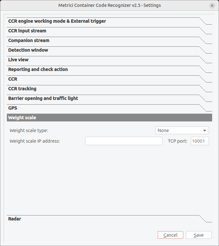
The weight scale feature connects the recognizer to a weighbridge or scale so that each recognized container can be paired with a measured weight. The weight is then included with the recognition event, giving you a single record that links the container code to its weight at the gate.
Configuration
- Weight scale type: Select the model of scale you are connecting from the dropdown. Set it to None if no scale is used — see Fig.12 Weight Scale.
- Weight scale IP address: The network address of the scale controller.
- TCP port: The port used to communicate with the scale (default
10001).
Radar
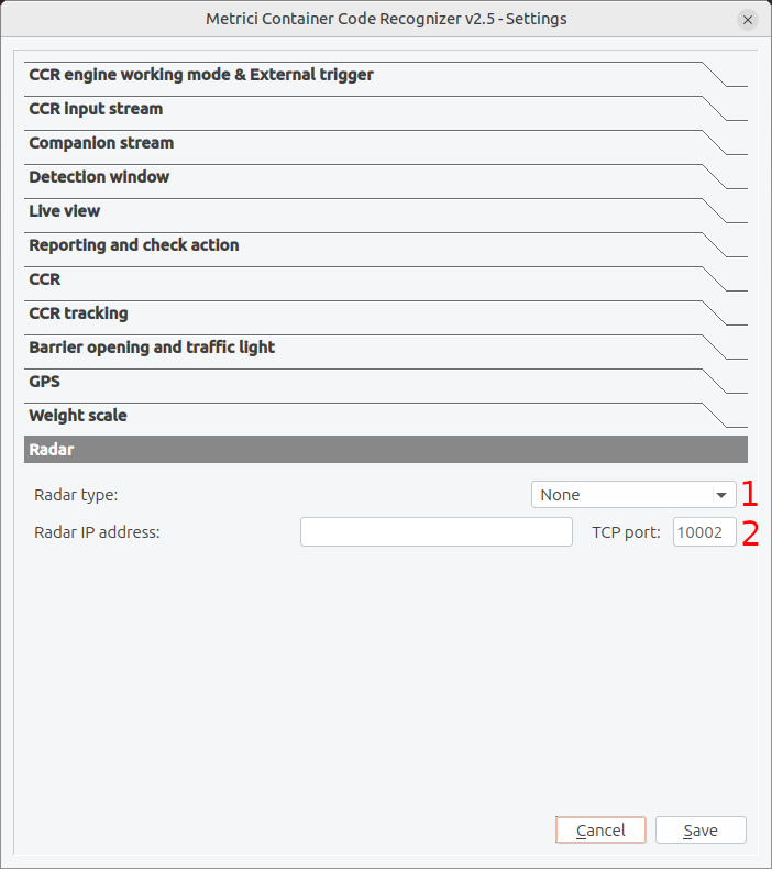
The radar feature connects the recognizer to a radar unit. A radar can detect the presence or speed of an approaching vehicle and is commonly used as the trigger that tells the engine when to start reading a code — see Engine Working Mode & External Trigger.
Configuration
- Radar type: Select the model of radar you are connecting from the dropdown. Set it to None if no radar is used — see Fig.13 Radar (1).
- Radar IP address / TCP port: The network address of the radar unit and the port used to communicate with it (default
10002) — see Fig.13 Radar (2).
Troubleshooting
Connection Issues
| Problem | Solution |
|---|---|
| Camera won't connect | Check the network cable, verify the IP address or snapshot URL, confirm the camera is powered on. |
| Connection drops frequently | Increase RTSP latency, check network stability, reduce video quality. |
| Wrong image or stream | Verify the stream address or snapshot path, check the camera configuration for the correct stream. |
| Authentication failed | Confirm the username/password, check for special characters that require URL encoding. |
Recognition Accuracy Issues
| Problem | Solution |
|---|---|
| Code not read | Check that the code passes inside the detection window; verify the CCR min./max. length values allow the code's pixel size. |
| Same code reported many times | Increase the Same CCR delay; enable Single CCR mode for single-lane gates. |
| Wrong direction (coming/leaving) | Re-check the CCR tracking arrow and dropdown so they match the real direction of travel. |
| False readings from other text | Tighten the detection window so it covers only where the code appears. |
Image Quality Issues
| Problem | Solution |
|---|---|
| Characters too small | Zoom or reposition the camera so the code is larger; raise the CCR minimum length accordingly. |
| Blurry images | Check camera focus; reduce motion blur with a higher shutter speed. |
| Glare or poor lighting | Add or reposition lighting; avoid direct sun or reflections on the container surface. |
Performance Issues
| Problem | Solution |
|---|---|
| Low frame rate | Use the detection window to limit the processed area, lower the FPS limit, reduce resolution. |
| High CPU usage | Use triggered mode with a sensor or radar so the engine runs only when a container is present. |
| Memory usage growing | Restart the application periodically, reduce video buffer sizes. |
Barrier & Traffic Light Issues
| Problem | Solution |
|---|---|
| Barrier not responding | Verify the URL is correct, check the barrier controller network connection, test the URL manually in a browser. |
| Barrier closes too fast | Increase the delay before closing the barrier. |
| Barrier opens unintentionally | Review the check action logic and the trigger configuration. |
| Traffic light stuck on or off | Confirm both the ON and OFF URLs are set, and check the delay between ON/OFF signals. |
Getting Help
If you continue experiencing issues:
- Check the application logs for detailed error messages.
- Note the exact conditions when the problem occurs.
- Contact technical support with:
- Application version
- Camera model and configuration
- Operating system details
- Error messages or log excerpts
Configuration File (INI File)
The Metrici Container Code Recognizer stores all its configuration settings in a file called
[app_id].ini, where [app_id] is the application identifier (typically a number).
This file is created automatically in the application directory when you first save your settings.
Understanding the INI File
The INI file is a standard configuration file format organized into key-value pairs. You can view or edit this file with any text editor, but it is recommended to use the application's Settings window for configuration changes to ensure all values are validated and saved correctly.
INI File Location
The INI file is stored in the same directory as the application executable. The filename matches your
application ID (e.g., 1.ini, 2.ini). Multiple INI files can exist for different
application instances.
Configuration Values Reference
The following tables list the main configuration values stored in the INI file, grouped by settings section, together with typical default values and a description of what each setting controls. Key names follow the standard Metrici naming convention; confirm them against your generated file if you edit it by hand.
Input Stream Settings
| Setting Name | Default Value | Description |
|---|---|---|
input_stream_type |
0 | Type of input stream (e.g. Generic JPEG Picture HTTP, RTSP, brand-specific driver). |
input_stream_address |
http://localhost/1.jpg | Network address, snapshot URL, or file path of the video source. |
input_stream_tcp_port |
8080 | Port number used to connect to the camera. |
input_stream_username |
(empty) | Username for camera authentication. |
input_stream_password |
(empty) | Password for camera authentication. |
input_stream_fps_limit |
0 | Maximum frames per second to process (0 = unlimited). |
input_stream_resx |
(from camera) | Width of the input video stream, in pixels. |
input_stream_resy |
(from camera) | Height of the input video stream, in pixels. |
input_stream_use_ssl |
0 | Use SSL/HTTPS for the input stream connection (0 = no, 1 = yes). |
rtsp_stream_latency |
100 | RTSP buffering delay, in milliseconds. |
rtsp_stream_protocols |
tcp | RTSP transport protocol to attempt (tcp, udp, or both). |
Companion Stream Settings
| Setting Name | Default Value | Description |
|---|---|---|
companion_stream_type |
(undefined) | Type of companion video stream. |
companion_stream_address |
(empty) | Network address or file path of the companion video source. |
companion_stream_tcp_port |
80 | Port number for the companion camera connection. |
companion_stream_username |
(empty) | Username for companion camera authentication. |
companion_stream_password |
(empty) | Password for companion camera authentication. |
companion_stream_resx |
640 | Width of the companion video stream, in pixels. |
companion_stream_resy |
480 | Height of the companion video stream, in pixels. |
companion_stream_use_ssl |
0 | Use SSL/HTTPS for the companion stream connection (0 = no, 1 = yes). |
Detection Window Settings
| Setting Name | Default Value | Description |
|---|---|---|
input_stream_window_active |
1 | Enable the detection window (0 = whole frame, 1 = restricted region). |
input_stream_window_origx |
231 | Horizontal position of the top-left corner, in pixels. |
input_stream_window_origy |
60 | Vertical position of the top-left corner, in pixels. |
input_stream_window_resx |
1072 | Width of the detection window, in pixels. |
input_stream_window_resy |
504 | Height of the detection window, in pixels. |
CCR & Tracking Settings
| Setting Name | Default Value | Description |
|---|---|---|
same_plate_delay |
3 | Seconds before the same container code can be reported again. |
plate_min_length |
100 | Minimum accepted length of a container code, in pixels. |
plate_max_length |
1000 | Maximum accepted length of a container code, in pixels. |
single_plate_mode |
1 | Track and report only one code at a time (0 = off, 1 = on). |
cars_direction |
0 | Movement direction (per the tracking arrow) treated as coming; the opposite is leaving. |
cars_event_type |
1 | Type of event generated for each recognition. |
Engine & Trigger Settings
| Setting Name | Default Value | Description |
|---|---|---|
lpr_engine_working_mode |
0 | Engine mode (0 = continuous, other = triggered). |
external_trigger_type |
0 | Trigger device and type (0 = none; other values select a hardware or virtual trigger). |
external_trigger_seconds |
1 | How many seconds the engine keeps analyzing after a trigger is received. |
Reporting & Check Action Settings
| Setting Name | Default Value | Description |
|---|---|---|
reporting_url |
http://localhost/io/ccr/reporting_event.php | URL where recognition events are sent. |
check_action_url |
http://localhost/io/ccr/check_action_event.php | URL contacted to validate a code and decide the action. |
check_action_send_trigger_address |
(empty) | IP address that receives a UDP trigger at check action. |
check_action_send_trigger_udp_port |
0 | UDP port for the check-action trigger (0 = disabled). |
reporting_check_action_authkey |
(empty) | Security key for authenticating reporting and check-action requests. |
reporting_check_action_id |
0 | Identifier for this recognizer instance in reporting. |
Live View Settings
| Setting Name | Default Value | Description |
|---|---|---|
live_view_active |
1 | Enable live view streaming (0 = disabled, 1 = enabled). |
live_view_url |
http://localhost/io/ccr/live_view.php | URL where the processed video stream is published. |
Barrier, Traffic Light, Weight Scale & Radar Settings
The engine drives two HTTP outputs: a main barrier and a second output (the *_barrier2_* keys). In the CCR interface the second output is presented as the traffic-light ON/OFF control — there are no separate traffic_light_* keys.
| Setting Name | Default Value | Description |
|---|---|---|
open_barrier_url |
(empty) | HTTP URL that opens the barrier. |
close_barrier_url |
(empty) | HTTP URL that closes the barrier. |
open_close_barrier_delay |
10 | Seconds the barrier stays open before auto-closing. |
open_barrier2_url |
(empty) | HTTP URL for the second output — opens the second barrier or sends the traffic-light ON signal. |
close_barrier2_url |
(empty) | HTTP URL for the second output — closes the second barrier or sends the traffic-light OFF signal. |
open_close_barrier2_delay |
10 | Delay for the second output, in seconds. |
weight_scale_type |
0 | Type of connected weight scale (0 = none). |
weight_scale_address |
(empty) | IP address of the weight scale controller. |
weight_scale_tcp_port |
10001 | TCP port for communicating with the weight scale. |
radar_type |
0 | Type of connected radar (0 = none). |
radar_address |
(empty) | IP address of the radar unit. |
radar_tcp_port |
10002 | TCP port for communicating with the radar. |
Example INI File
Below is an example of what a typical INI file looks like with sample configuration values:
[General]
cars_direction=0
cars_event_type=1
check_action_send_trigger_address=
check_action_send_trigger_udp_port=0
check_action_url=http://localhost/io/ccr/check_action_event.php
close_barrier2_url=
close_barrier_url=
companion_stream_address=
companion_stream_password=
companion_stream_resx=640
companion_stream_resy=480
companion_stream_tcp_port=80
companion_stream_type=0
companion_stream_use_ssl=0
companion_stream_username=
external_trigger_seconds=1
external_trigger_type=0
input_stream_address=http://localhost/1.jpg
input_stream_fps_limit=0
input_stream_password=
input_stream_resx=4284
input_stream_resy=5712
input_stream_tcp_port=8080
input_stream_type=33
input_stream_use_ssl=0
input_stream_username=
input_stream_window_active=0
input_stream_window_origx=668
input_stream_window_origy=1188
input_stream_window_resx=668
input_stream_window_resy=1188
live_view_active=1
live_view_url=http://localhost/io/ccr/live_view.php
lpr_engine_working_mode=0
open_barrier2_url=
open_barrier_url=
open_close_barrier2_delay=10
open_close_barrier_delay=10
plate_max_length=1000
plate_min_length=100
radar_address=
radar_tcp_port=10002
radar_type=0
reporting_check_action_authkey=
reporting_check_action_id=0
reporting_url=http://localhost/io/ccr/reporting_event.php
rtsp_stream_latency=100
rtsp_stream_protocols=tcp
same_plate_delay=3
single_plate_mode=1
weight_scale_address=
weight_scale_tcp_port=10001
weight_scale_type=0Multiple Configuration Files
You can create multiple INI files for different configurations by changing the application ID. This is useful for:
- Different camera setups at different gates or locations.
- Testing new settings without affecting the production configuration.
- Switching between different recognition scenarios.
Simply copy the INI file with a different name and configure the application to use that file.
Glossary
Anatomy of a Container Code (ISO 6346)
A standard container identification code is made up of four parts. Using the example
CFSU 000560 [1] shown in this manual:
| Part | Example | Meaning |
|---|---|---|
| Owner code | CFS | Three letters identifying the container's registered owner or principal operator. |
| Equipment category identifier | U | One letter for the equipment type: U = freight container, J = detachable equipment, Z = trailer/chassis. |
| Serial number | 000560 | Six digits assigned by the owner to uniquely identify the unit. |
| Check digit | [1] | A single digit, calculated from the preceding characters, used to validate that the code was read correctly. |
The code is usually displayed together with a four-character size/type code (for example
22G1), which encodes the container's dimensions and construction type.
Terms
- Container Code (CC)
- The ISO 6346 identification code marked on a container, read by the recognizer.
- Check Digit
- The final digit of a container code, used to confirm the rest of the code was read correctly.
- Check Action
- A request to an external system to validate a recognized code and decide what should happen next, such as opening a barrier.
- Detection Window
- The rectangular region of the image in which the engine searches for a container code.
- FPS
- Frames Per Second — a measure of how many images per second are processed.
- ISO 6346
- The international standard that defines the coding, identification, and marking of shipping containers.
- Owner Code
- The three-letter prefix of a container code that identifies its registered owner.
- RTSP
- Real Time Streaming Protocol — a standard protocol for streaming video over networks.
- Size/Type Code
- A four-character code (e.g. 22G1) describing a container's dimensions and type.
- Trigger
- A signal (from hardware or software) that causes the system to start recognition or take an action.