Metrici Thermal Analyzer v1.2
User Manual for End Users and System Administrators

Welcome to the Metrici Thermal Analyzer user manual. This document will guide you through all the features and settings of the application, helping you to effectively use it for thermal image analysis and people/object counting.
Table of Contents
- 1. Introduction
- 2. Getting Started
- 3. Main Window Overview
- 4. Connecting to Camera Streams
- 5. Setting Up Counting Zones
- 6. Image Processing Settings
- 7. Thermal Measurement Configuration
- 8. Triggers and External Actions
- 9. Reporting and Integration
- 10. Advanced Settings
- 11. Configuration File (INI)
- 12. Troubleshooting
1. Introduction
What is Metrici Thermal Analyzer?
Metrici Thermal Analyzer is a software application designed to process thermal imaging video streams and perform automated detection and counting of people or objects and measure temperatures. The application connects to various types of thermal and visual cameras, analyzes the video feed in real-time, and can trigger external actions based on detection events and temperatures.
Key Features
- Multi-Protocol Support: Connect to cameras using RTSP, HTTP MJPEG, and other common protocols from manufacturers like Axis, Bosch, Hikvision, Mobotix, and many others.
- Thermal Analysis: Measure temperature from thermal camera data and set up temperature alarms.
- People/Object Counting: Define counting zones and track how many objects enter or exit these zones.
- Real-time Processing: Process video streams in real-time with GPU acceleration support for improved performance.
- External Integration: Trigger external systems like barrier controllers or send reports to servers when events occur.
- Dual Stream Support: Process both thermal and visual camera streams simultaneously for enhanced analysis.
2. Getting Started
Starting the Application
The application can be started in two modes:
- Graphical Mode (Default): Run without any command-line arguments to launch the full graphical interface — the app starts automatically when the server is on.
- No-GUI Mode: Use the
-noguicommand-line argument to run the application without the graphical interface, useful for headless servers or automated deployments.
Command-Line Options
| Option | Description |
|---|---|
./metrici-ta -nogui |
Run without graphical interface |
./metrici-ta -disable_gpu |
Disable GPU acceleration even if available |
./metrici-ta -use_gpu <id> |
Select specific GPU device by ID (if multiple GPUs available) |
./metrici-ta -detection_threads <n> |
Number of processing threads (1-8, default: 1) |
./metrici-ta -gpu <id> |
Set GPU device ID for OpenCL |
./metrici-ta -app_id <id> |
Application instance ID (0-254) |
./metrici-ta -log_level <level> |
Logging level (0=None, 1=Low, 2=Medium, 3=High) |
3. Main Window Overview
The main window is the central hub for monitoring and controlling the application. It displays video streams, counting statistics, and provides access to all configuration options.
Main Window Components
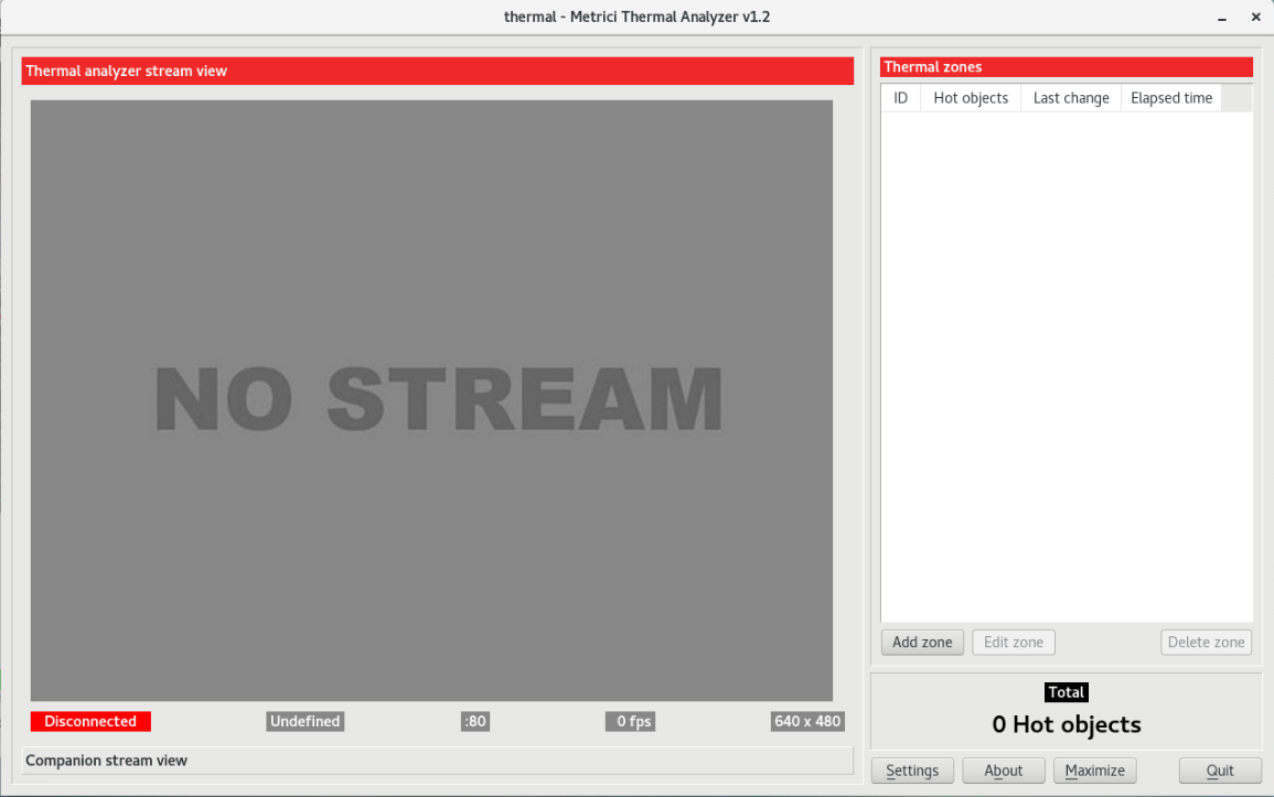
3.1 Video Display Area
The video display area shows the processed video stream. This is where you can:
- View the live video feed from your camera
- See detection overlays showing detected objects
- View counting zones that you have configured
- Observe temperature measurements (from thermal cameras)
3.2 Connection Status Indicators
Connection status indicators show the current state of your camera connections:
- Connected: Green indicator when successfully receiving video
- Connecting: Yellow indicator during connection attempt
- Disconnected: Red indicator when connection is lost
3.3 FPS Counter
The frames per second (FPS) counter shows how many video frames are being processed each second. This helps you understand if your system is keeping up with the video stream.
3.4 Control Buttons
| Button | Function |
|---|---|
| Settings | Open the settings window to configure all application options |
| About | Display version information and application details |
| Quit | Close the application |
| Maximize | Make the image bigger |
3.5 Total Counter Display
The total counter display shows the cumulative count of objects detected across all counting zones. This provides a quick overview of detection activity.
4. Connecting to Camera Streams
One of the first steps in setting up the application is configuring your camera connections. The application supports a wide variety of camera types and connection protocols.
4.1 Input Stream Configuration
The input stream is your primary video source, typically a thermal camera. Configure these settings in the Settings window under the Input Stream section.
Stream Type
Select the appropriate camera manufacturer and protocol from the dropdown list. The application supports cameras from:
- ACTi - Both MJPEG over HTTP and H264 over RTSP
- AXIS - MJPEG and H264 streams over HTTP and RTSP
- Bosch - Professional surveillance cameras
- DAHUA - Popular IP cameras
- DIVIOTEC - Thermal cameras
- Hikvision - Major camera manufacturer
- Mobotix - German cameras with MJPEG and MxPEG formats
- Samsung - Consumer and professional cameras
- Sony - Various IP camera models
- Generic Cameras - For cameras that don't match specific brands
- Roseek RAW - Special raw thermal data format
Stream Address
Enter the network address of your camera. The format depends on your camera type:
- HTTP MJPEG:
http://camera_ip_address/video.cgior similar path - RTSP H264:
rtsp://camera_ip_address:554/stream1 - JPEG Picture:
http://camera_ip_address/cgi-bin/currentpic.cgi
TCP Port (for RTSP streams)
Specify the TCP port number for RTSP streams (default is typically 554).
Username and Password
Enter the authentication credentials required to access your camera. Most IP cameras require a username and password for access.
FPS Limit
Set a maximum frames per second limit for the video stream. This can be useful for reducing system load or when you don't need full-speed processing.
4.2 Companion Stream Configuration
The companion stream is an optional secondary video source, typically a visual (non-thermal) camera that provides a clearer view for visual verification. Configure these settings in the Settings window under the Companion Stream section.
The companion stream uses the same configuration options as the input stream. Having both thermal and visual streams allows for visual confirmation of thermal findings.
5. Setting Up Counting Zones
Counting zones are defined areas within the video frame where the application tracks objects entering or exiting. This feature is essential for accurate counting statistics.
5.1 Creating Counting Zones
- Click the Add Zone button in the main window
- A new zone will appear in the zones table
- Use your mouse to define the zone boundaries on the video display
- Click Save Zone when finished
5.2 Zone Geometry
Each counting zone is defined by four points (corners) that form a quadrilateral:
- Point 1 (x1, y1): Top-left corner of the zone
- Point 2 (x2, y2): Top-right corner of the zone
- Point 3 (x3, y3): Bottom-right corner of the zone
- Point 4 (x4, y4): Bottom-left corner of the zone
The application uses these four points to create a polygon that defines the counting area. Objects detected within this polygon are tracked and counted.
5.3 Zone Management
| Action | Description |
|---|---|
| Add Zone | Create a new counting zone |
| Edit Zone | Modify an existing zone's shape or position |
| Save Zone | Save changes to the current zone |
| Delete Zone | Remove the selected zone |
5.4 Zone Counting Logic
The application tracks objects as they move through counting zones:
- When an object enters a zone from outside, the counter increments
- When an object exits a zone, the counter decrements
- The net count shows the current number of objects within the zone
6. Image Processing Settings
Image processing settings control how the application analyzes video frames and detects objects. Proper configuration of these settings is crucial for accurate detection.
6.1 Engine Working Mode
| Mode | Description |
|---|---|
| Continuous | The application constantly processes video frames and updates detections in real-time |
| Started by Trigger | Processing only occurs when an external trigger signal is received |
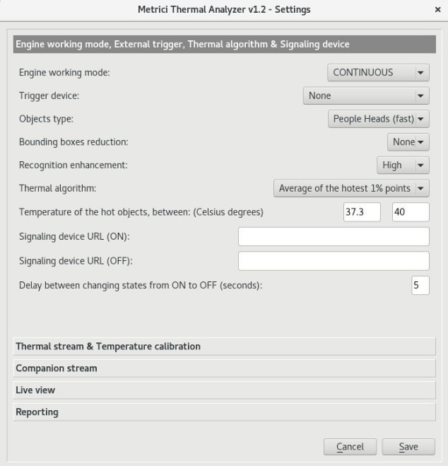
6.2 Recognition Enhancement
This setting controls the sensitivity and accuracy of the detection algorithm:
| Level | Description | Best For |
|---|---|---|
| Low | Fastest processing, lower detection accuracy | Low-power systems, simple scenes with large, clearly visible objects |
| Medium | Balanced speed and accuracy | General purpose use |
| Normal | Standard detection quality | Default for most scenarios |
| High | Higher accuracy, slower processing | Challenging lighting or crowded scenes |
| Ultra | Very high accuracy, significant processing overhead | Critical applications, high-end systems |
| Insane | Maximum accuracy, maximum processing requirements | Best systems only, when accuracy is paramount |
6.3 Objects Type
Select what type of objects the application should detect:
| Type | Description |
|---|---|
| People | Detect full human bodies using standard detection model |
| People (fast) | Detect people using a faster, lightweight DNN model |
| People Heads | Detect only human heads (useful for thermal cameras) |
| People Heads (fast) | Detect heads using lightweight model |
6.4 Bounding Boxes Reduction
This setting reduces the size of detection bounding boxes, which can help with overlapping detections:
| Reduction | Effect |
|---|---|
| None (0%) | Full bounding box size |
| 10%-90% | Progressively smaller bounding boxes |
6.5 Image Mode
| Mode | Description |
|---|---|
| Single Sensor | Process video from one camera only |
| Dual Sensor | Process both streams simultaneously |
6.6 Counter Change Delay
Set a delay (in seconds) before counting changes are registered. This helps prevent double-counting due to rapid re-detection of the same object.
7. Thermal Measurement Configuration
For thermal cameras, the application can measure temperature and trigger alarms when temperatures exceed defined thresholds.
7.1 Thermal Sensor Selection
If using a dual-sensor setup, select which thermal sensor to use:
| Option | Description |
|---|---|
| RIGHT | Use the right thermal sensor only |
| LEFT | Use the left thermal sensor only |
| LEFT + RIGHT | Combine data from both sensors |
7.2 Temperature Algorithm
Select how temperature is calculated from the thermal data:
| Algorithm | Description |
|---|---|
| Average Temperature | Calculate the average temperature across all pixels |
| Average of Hottest 10% | Average temperature of the hottest 10% of pixels |
| Average of Hottest 1% | Average temperature of the hottest 1% of pixels |
| Hottest Point | Use the maximum temperature from a single pixel |
7.3 Temperature Alarms
Configure minimum and maximum temperature thresholds:
- Minimum Temperature: Triggers an alarm if temperature falls below this value
- Maximum Temperature: Triggers an alarm if temperature exceeds this value
When a temperature alarm is triggered, the application can send notifications or trigger external actions (see Section 8).
7.4 Temperature Calibration
Configure how temperature measurements are calibrated:
| Calibration Type | Description |
|---|---|
| None | Use raw temperature data without calibration |
| Static Deviation | Apply a fixed offset to all temperature readings |
| Black Body | Use a reference black body source for calibration (most accurate) |
7.5 Static Deviation
If using "Static Deviation" calibration, enter the temperature offset value (positive or negative) to adjust all readings.
7.6 Bounding Box for Temperature
For "Black Body" calibration, define the bounding box coordinates that specify the area of the camera image containing the black body reference:
- X Position: Horizontal position of the black body area
- Y Position: Vertical position of the black body area
- Width: Width of the black body area
- Height: Height of the black body area
- Expected Temperature: The known temperature of the black body reference
8. Triggers and External Actions
The application can respond to external triggers and perform actions when certain events occur.
8.1 External Trigger Configuration
Configure how the application responds to external trigger signals:
Trigger Type
| Type | Description |
|---|---|
| None | No external trigger functionality |
| Barix Barionet 50 (Input 1-4) | Listen for triggers from Barix Barionet 50 device inputs |
| Metrici Virtual Trigger | Software-based trigger from Metrici system — other detection engines |
8.2 Signaling Device Control
The application can control barrier/gates/lights etc systems by sending HTTP requests when events occur.
Signaling Device URL (ON)
Enter the HTTP URL that will open the device. When the application needs to open the barrier or command other device (e.g., when detecting a person in a zone), it will send a request to this URL.
Signaling Device URL (OFF)
Enter the HTTP URL that will close the device. When the application needs to close it, it will send a request to this URL.
Open/Close Delay
Set the delay (in seconds) between open and close actions. This determines how long the device stays open/ON.
9. Reporting and Integration
The application can send reports to external servers when counting events occur, enabling integration with other systems.
9.1 Reporting URL
Enter the URL of the server endpoint that will receive counting event reports. The application will send HTTP requests to this URL when objects are detected in counting zones.
http://localhost/io/ta/new_counting_zone_event.php
Hot objects count delay is the time interval to pass between detecting an object and a counter change and the moment the change is reported. It is meant to prevent false positives.
Auth Key
Enter an authentication key that is generated by Metrici in the Interface when creating the location and the camera. This facilitates the communication between the detection engines and the interface/database. It is mandatory for the system to work. Fill in here data from Metrici Interface.
9.2 Live View
The application can provide a live view feed for web-based monitoring.
Live View Active
Enable or disable the live view feature.
Live View URL
Enter the URL where the live view feed will be available. This is typically a local server endpoint that streams the processed video, as in http://localhost/io/ta/live_view.php.
10. Advanced Settings
Advanced settings provide additional configuration options for power users and specific use cases.
10.1 GPU Acceleration
The application can use GPU acceleration for faster image processing. GPU processing is significantly faster than CPU processing for detection algorithms.
Multiple GPU Systems
On systems with multiple GPUs, you can specify which GPU to use with the -gpu <id> command-line argument, where <id> is the GPU index, or on the main window edit the application.
10.2 Processing Threads
The number of processing threads determines how many parallel tasks the application can run. More threads can improve throughput on multi-core systems.
10.3 Logging Level
Configure how much information is recorded to the application log:
| Level | Description |
|---|---|
| None | No logging (fastest performance) |
| Low | Only critical events and errors |
| Medium | Standard logging including warnings |
| High | Verbose logging including detailed debug information |
11. Configuration File (INI)
The application stores all its configuration settings in a configuration file called <app_id>.ini, where <app_id> is the application instance ID (default: 0.ini).
This file is automatically created and updated by the application when you save settings.
11.1 INI File Location
The INI file is located in the same directory as the application executable. If you run multiple instances of the application with different app_id values, each instance will use its own corresponding INI file (0.ini, 1.ini, 2.ini, etc.).
11.2 INI File Structure
The INI file is divided into sections, with all application settings stored under the [General] section. Each setting is stored as a key-value pair on its own line.
[General]
input_stream_type=30
input_stream_address=192.168.100.78
input_stream_tcp_port=80
input_stream_username=admin
input_stream_password=admin123
input_stream_fps_limit=0
companion_stream_type=33
companion_stream_address=http://192.168.100.78/cgi-bin/image.jpg
companion_stream_tcp_port=80
companion_stream_username=admin
companion_stream_password=admin123
reporting_check_action_authkey=597SX5D4
reporting_check_action_id=420
reporting_url=http://dev2.metrici.ro/io/ta/new_counting_zone_event.php
reporting_duplicate_url=
input_stream_resx=1280
input_stream_resy=480
companion_stream_resx=640
companion_stream_resy=480
live_view_active=1
live_view_url=http://dev2.metrici.ro/io/ta/live_view.php
external_trigger_type=0
external_trigger_seconds=1
engine_working_mode=0
recognition_enhancement=2
objects_type=2
bounding_boxes_reduction=5
counter_change_delay=1
counting_zones_list=1,0.978957,0.028057,0.982617,0.942970,0.523750,0.940000,0.513750,0.033333;
image_mode=1
thermal_sensor=0
thermal_algorithm=1
alarm_min_temperature=36
alarm_max_temperature=40
temperature_calibration=2
temperature_static_deviation=-3.3
temperature_bbody_x=0.500391
temperature_bbody_y=0.003125
temperature_bbody_w=0.0890625
temperature_bbody_h=0.204167
temperature_bbody_t=40
open_barrier_url=http://support.metrici.ro/sn.php
open_close_barrier_delay=3
close_barrier_url=http://support.metrici.ro/sn.php
fullscreen=0
11.3 Complete INI Settings Reference
The following table lists all possible settings that can be stored in the INI file:
Input Stream Settings
| Setting Name | Description | Values |
|---|---|---|
input_stream_type |
Camera type and protocol for the primary stream | 1-35 (see Stream Type Reference) |
input_stream_address |
Network address (IP or hostname) of the camera | String (e.g., "192.168.100.78") |
input_stream_tcp_port |
TCP port for RTSP streams | Number (default: 554) |
input_stream_username |
Username for camera authentication | String (leave empty if no auth) |
input_stream_password |
Password for camera authentication | String (leave empty if no auth) |
input_stream_fps_limit |
Maximum frames per second to process | 0 = unlimited, or number (e.g., 15) |
input_stream_resx |
Expected horizontal resolution of input stream | Number (pixels, e.g., 1280) |
input_stream_resy |
Expected vertical resolution of input stream | Number (pixels, e.g., 480) |
Companion Stream Settings
| Setting Name | Description | Values |
|---|---|---|
companion_stream_type |
Camera type and protocol for the secondary stream | 0 = disabled, 1-35 for types |
companion_stream_address |
Network address of the companion camera | String or empty |
companion_stream_tcp_port |
TCP port for companion RTSP stream | Number |
companion_stream_username |
Username for companion camera | String or empty |
companion_stream_password |
Password for companion camera | String or empty |
companion_stream_resx |
Expected horizontal resolution of companion stream | Number (pixels) |
companion_stream_resy |
Expected vertical resolution of companion stream | Number (pixels) |
Reporting Settings
| Setting Name | Description | Values |
|---|---|---|
reporting_url |
URL endpoint for sending counting event reports | HTTP URL string or empty |
reporting_duplicate_url |
Secondary URL for redundant reporting | HTTP URL string or empty |
reporting_check_action_id |
Application identifier included in reports | Number (e.g., 420) |
reporting_check_action_authkey |
Authentication key for report verification | String (e.g., "597SX5D4") |
Live View Settings
| Setting Name | Description | Values |
|---|---|---|
live_view_active |
Enable or disable live view feature | 0 = disabled, 1 = enabled |
live_view_url |
URL for the live view streaming endpoint | HTTP URL string or empty |
External Trigger Settings
| Setting Name | Description | Values |
|---|---|---|
external_trigger_type |
Type of external trigger input | 0=None, 1-4=Barix inputs, 5=Virtual |
external_trigger_seconds |
Timeout in seconds for trigger detection | Number (e.g., 1) |
Image Processing Settings
| Setting Name | Description | Values |
|---|---|---|
engine_working_mode |
How the detection engine operates | 0=Continuous, 1=Started by Trigger |
recognition_enhancement |
Detection sensitivity level | 0=Low, 1=Medium, 2=Normal, 3=High, 4=Ultra, 5=Insane |
objects_type |
Type of objects to detect | 0=People, 1=People(fast), 2=Heads, 3=Heads(fast) |
bounding_boxes_reduction |
Percentage to reduce bounding box size | 0-9 (0=None, 9=90%) |
counter_change_delay |
Delay before counting changes (1/100 sec) | Number (e.g., 1) |
image_mode |
Single or dual sensor processing | 0=Single, 1=Dual |
status_change_delay |
Delay before status changes (alternative setting) | Number (seconds) |
Counting Zones
| Setting Name | Description | Values |
|---|---|---|
counting_zones_list |
List of defined counting zones with coordinates | Zone data format: ID,x1,y1,x2,y2,x3,y3,x4,y4,counter; |
Each zone is represented by:
ID,x1,y1,x2,y2,x3,y3,x4,y4,counter;Example:
1,0.978957,0.028057,0.982617,0.942970,0.523750,0.940000,0.513750,0.033333;This creates Zone 1 with the coordinates of its four corners.
Thermal Measurement Settings
| Setting Name | Description | Values |
|---|---|---|
thermal_sensor |
Which thermal sensor(s) to use | 0=Right, 1=Left, 2=Both |
thermal_algorithm |
Temperature calculation method | 0=Average, 1=Avg10%, 2=Avg1%, 3=Hottest |
alarm_min_temperature |
Minimum temperature threshold for alarms | Number (e.g., 36.0) |
alarm_max_temperature |
Maximum temperature threshold for alarms | Number (e.g., 40.0) |
temperature_calibration |
Calibration method | 0=None, 1=Static, 2=BlackBody |
temperature_static_deviation |
Fixed temperature offset for calibration | Number (positive or negative, e.g., -3.3) |
temperature_bbody_x |
Black body bounding box X position (0-1 normalized) | Decimal (e.g., 0.500391) |
temperature_bbody_y |
Black body bounding box Y position (0-1 normalized) | Decimal (e.g., 0.003125) |
temperature_bbody_w |
Black body bounding box width (0-1 normalized) | Decimal (e.g., 0.0890625) |
temperature_bbody_h |
Black body bounding box height (0-1 normalized) | Decimal (e.g., 0.204167) |
temperature_bbody_t |
Known temperature of black body reference | Number (e.g., 40.0) |
Barrier Control Settings
| Setting Name | Description | Values |
|---|---|---|
open_barrier_url |
HTTP URL to open the barrier/gate | HTTP URL string or empty |
close_barrier_url |
HTTP URL to close the barrier/gate | HTTP URL string or empty |
open_close_barrier_delay |
Time in seconds barrier stays open | Number (e.g., 3) |
Display Settings
| Setting Name | Description | Values |
|---|---|---|
fullscreen |
Start application in fullscreen mode | 0=windowed, 1=fullscreen |
11.4 Manually Editing the INI File
While the application automatically creates and updates the INI file when you save settings, you can also edit it manually for advanced configurations or bulk changes.
Best Practices for INI File Editing
- Make a backup: Copy the INI file before making changes
- Use a text editor: Use a plain text editor (not a word processor)
- Preserve format: Keep the same line format (key=value)
- Restart application: Application usually takes automatically the new settings after saving changes
11.5 INI File for Multiple Instances
When running multiple instances of the application on the same system, each instance uses a separate INI file based on its application ID:
- Instance with
app_id=0uses0.ini - Instance with
app_id=1uses1.ini - Instance with
app_id=2uses2.ini - And so on...
This allows each instance to have completely independent configurations, including different camera connections, counting zones, and reporting settings.
11.6 Transferring Configuration
To transfer your configuration to another system or create identical setups on multiple machines:
- Copy the entire application directory including the INI file
- Ensure the same application ID is used on the new system
- Update IP addresses if cameras are at different network locations
- Test the configuration after transfer
12. Troubleshooting
12.1 Connection Issues
Camera Not Connecting
- Verify the camera IP address is correct and accessible
- Check that the stream type matches your camera model
- Ensure username and password are correct
- Check network connectivity and firewall settings
- Try using generic stream types if your camera brand isn't listed
Intermittent Connection
- Reduce the FPS limit to decrease network bandwidth
- Check for network stability issues
12.2 Detection Issues
No Objects Detected
- Verify the video stream is being received properly
- Check that the recognition enhancement level is appropriate
- Ensure the correct object type is selected
- Verify counting zones are properly defined and visible
False Positives
- Increase the recognition enhancement level
- Reduce bounding box overlap by increasing bounding box reduction
- Adjust counting zones
Double Counting
- Increase the counter change delay setting
- Make counting zones narrower or better defined
12.3 Performance Issues
Slow Frame Rate
- Enable GPU acceleration if available
- Reduce the recognition enhancement level
- Limit FPS to a lower value
- Use a faster object type (e.g., "People (fast)")
- Add processing threads if you have multiple CPU cores
High CPU Usage
- Enable GPU acceleration
- Lower the recognition enhancement level
- Reduce FPS limit
- Use fewer processing threads
12.4 Thermal Measurement Issues
Temperature Readings Seem Incorrect
- Apply proper calibration (static deviation or black body)
- Verify the temperature algorithm matches your use case
- Check environmental factors that might affect readings
- Ensure the correct thermal sensor is selected
Temperature Alarms Not Triggering
- Verify minimum/maximum thresholds are set correctly
- Check that the temperature algorithm is producing valid readings
- Ensure alarm functionality is enabled
12.5 Getting Help
If you encounter issues not covered in this manual:
- Check the application log for error messages (use higher logging level)
- Consult your system administrator for network or integration issues
- Contact technical support with detailed information about the problem
Appendix: Stream Type Reference
| Camera Brand | MJPEG HTTP | MJPEG RTSP | H264 RTSP |
|---|---|---|---|
| ACTi | Yes | No | Yes |
| Android | Yes | No | No |
| Arecont | Yes | No | No |
| AXIS | Yes | Yes | Yes |
| Bosch | No | Yes | Yes |
| DAHUA | Yes | No | No |
| DIVIOTEC | Yes | No | Yes |
| Hikvision | Yes | No | Yes |
| Mobotix | Yes | No | Yes |
| Novus | Yes | No | Yes |
| Pelco | No | Yes | No |
| Samsung | Yes | No | Yes |
| Sony | Yes | No | Yes |
| Uniview | No | No | Yes |
| Vivotek | Yes | No | No |
| VLC | Yes | No | No |
| Generic | Yes | Yes | Yes |
Document Version: 1.1
Last Updated: February 2026
Application Version: Metrici Thermal Analyzer v1.2