Metrici Horn Light
User Manual for End Users and System Administrators

Drag to rotate • Scroll to zoom • Right-click to move
Table of Contents
1. Introduction
The Metrici Horn Light is a hardware product developed by Metrici. It is a compact LAN device with a built-in red indicator light and an audible horn — used to deliver simultaneous visual and audio alerts at parking entrances, access control points, or any location where an immediate go/stop signal is needed.
The device features a single Ethernet port that provides both network connectivity and electrical power via PoE (Power over Ethernet). No separate power adapter is needed — a single cable handles everything.
The red light and horn are controlled via two independent relay outputs built into the controller. When a Metrici detection engine (such as Area Counter or Line Counter) needs to signal an event, it sends an HTTP command to the Horn Light device, which activates the corresponding relay. For example, when a parking zone is full, the engine can trigger Relay 1 to turn the red light on and Relay 2 to sound the horn — alerting users that no space is available.
The controller is also managed through a web-based interface accessible from any browser on the same network. From this interface, you can manually activate the light and horn, set automatic timers, configure the network connection, manage user credentials, and perform firmware updates.
Key features:
- Red indicator light + horn — activate simultaneously on trigger for combined visual and audio alerts
- Two independent relay outputs — Relay 1 (red light) and Relay 2 (horn) with individually configurable timers
- Two input addresses — configure IP:port pairs to receive trigger signals from external systems
- Wiegand integration — connect to a Wiegand server for access control scenarios
- Automatic timers — set how long each output stays active before automatically switching off
- PoE powered — single Ethernet cable for both power and network
- Web interface — configure and monitor from any browser
- WiFi and Ethernet — supports both connection types
- Remote control via HTTP — outputs are controlled by Metrici detection engines (Area Counter, Line Counter, etc.) through simple HTTP commands
Technical Data
| Specification | Details |
|---|---|
| Description | Red light + horn alert LAN controller with built-in relay outputs |
| Outputs | Relay 1 (red indicator light), Relay 2 (horn/buzzer) |
| Inputs | 2 configurable input addresses (IP:port) |
| Connectivity | 1 Ethernet port (PoE) |
| Networking | WiFi 802.11 b/g/n and Ethernet 10/100 Mbps |
| Protocols | HTTP over TCP/IP, Wiegand |
| Power | PoE (IEEE 802.3af) via Ethernet cable — no separate power adapter needed |
| Operating Temperature | -20 to +50 °C, IP65 |
| Software Compatibility | Metrici v3.3 and higher |
| Interface | Web-based dashboard with 3 sections: Dashboard, Settings, User |
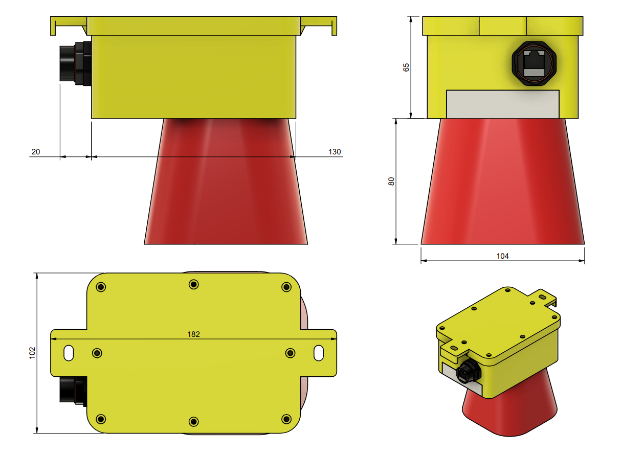
Dimensions
2. First Boot
The Metrici Horn Light is powered via PoE (Power over Ethernet). Connect a single Ethernet cable from a PoE switch or PoE injector to the device's Ethernet port. This cable provides both network connectivity and electrical power — no separate power adapter is needed.
After connecting the Ethernet cable, open a browser on a computer or phone connected to the same network and navigate to:
http://192.168.100.10
The device ships with factory defaults: Connection Type: Ethernet and IP Type: Static. This is why you can connect to it immediately at the default address using an Ethernet cable.
The web interface has three main sections:
- Dashboard — displays the current status of the device, network information, relay states, and logs
- Settings — where all configuration changes are made (network, I/O timers, Wiegand, backup, firmware)
- User — where a user account is created or edited for securing access to the interface
3. Dashboard
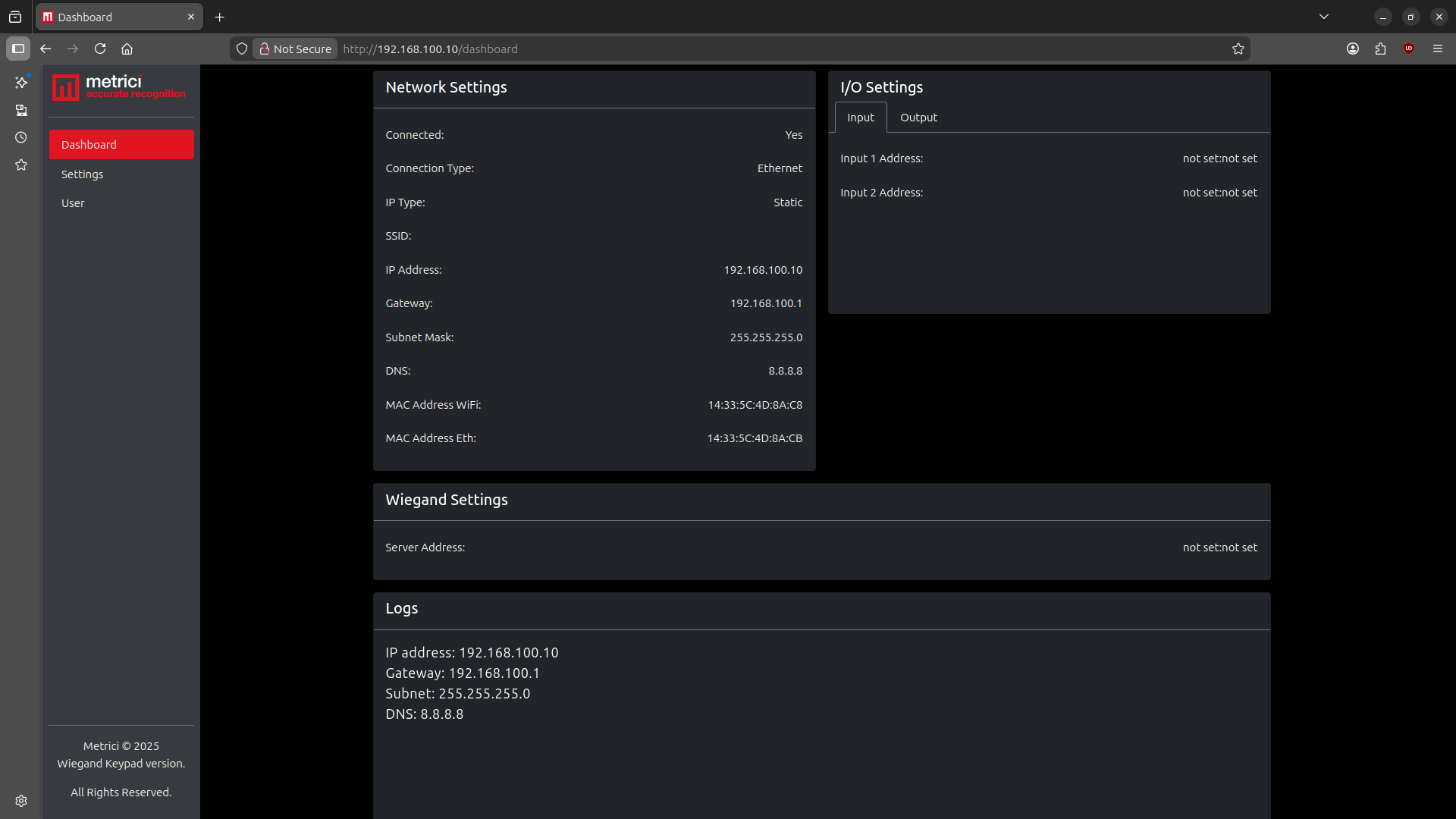
The Dashboard is the first page you see after accessing the device. It provides a real-time overview of the Horn Light device's current state — see Fig.1 Dashboard.
Network Status
The left side of the Dashboard displays the current network configuration, including:
- Connected — whether the device is connected to the network (Yes/No)
- Connection Type — Ethernet or WiFi
- IP Type — Static or DHCP
- SSID — the WiFi network name (empty when using Ethernet)
- IP Address — the device's current IP address
- Gateway — the router's IP address
- Subnet Mask — the network mask
- DNS — the DNS server address
- MAC Address WiFi — the device's WiFi MAC address
- MAC Address Eth — the device's Ethernet MAC address
Output Controls
The right side of the Dashboard shows the I/O Settings panel. Switch to the Output tab to view and manually control the device's relay outputs — see Fig.2 Dashboard Output Tab.
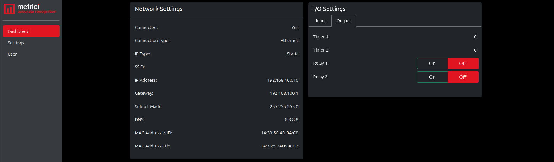
The Output tab provides:
- Timer 1 — displays the current timer value (in seconds) configured for Relay 1 (red light)
- Timer 2 — displays the current timer value (in seconds) configured for Relay 2 (horn)
- Relay 1 — On / Off — manual toggle to activate or deactivate the red indicator light
- Relay 2 — On / Off — manual toggle to activate or deactivate the horn
The On/Off buttons allow to manually control each output directly from the Dashboard for testing or manual operation. When a button is active (relay is on), the On button is highlighted. When inactive, the Off button is highlighted in red. Under normal triggered operation both relays activate at the same time — the red light turns on and the horn sounds simultaneously.
Logs
The Logs section at the bottom of the Dashboard displays a timestamped record of recent device events, including network configuration details and relay state changes. For example:
Relay 1 is ON— the red light was activatedRelay 1 is OFF— the red light was deactivatedRelay 2 is ON— the horn was activatedRelay 2 is OFF— the horn was deactivated
Logs are useful for troubleshooting and verifying that commands are being received and executed correctly.
4. Settings
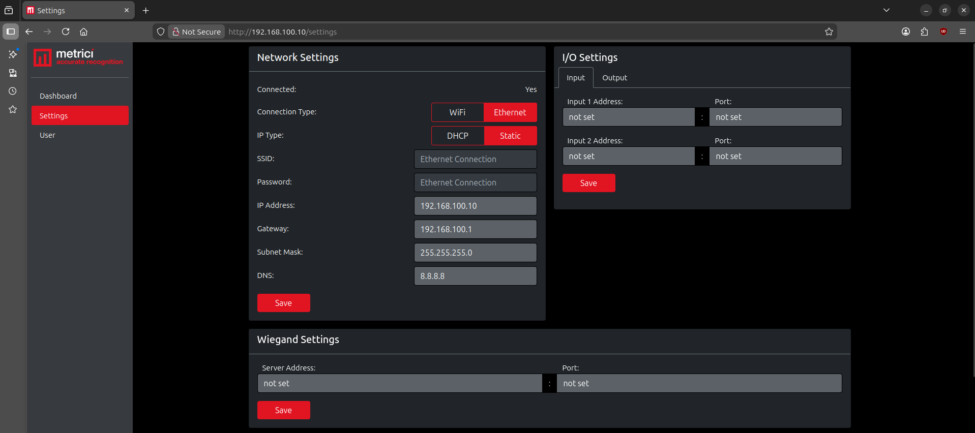
To configure the Horn Light device, click Settings in the left-side menu — see Fig.3 Settings. Here you can change the network configuration, set relay timers, configure input and Wiegand addresses, perform backup and restore operations, and update the firmware.
4.1 Network Settings
The Network Settings section allows you to configure how the device connects to your local network.
Connection Type
| Option | Description |
|---|---|
| Ethernet | Connect via Ethernet cable (recommended). SSID and Password fields become inactive and display "Ethernet Connection". |
| WiFi | Connect via WiFi. Enter the SSID and Password of your local wireless network. WE do not recommend using it. |
IP Type
| Option | Description |
|---|---|
| Static | Manually set the IP Address, Gateway, Subnet Mask, and DNS. Recommended for permanent installations so the device always has the same address. |
| DHCP | The device receives an IP address automatically from the router. All address fields become inactive. |
Network Fields
| Field | Description |
|---|---|
| SSID | The WiFi network name. Only used when Connection Type is WiFi. |
| Password | The WiFi network password. Only used when Connection Type is WiFi. |
| IP Address | The device's unique address on the network (e.g., 192.168.100.10). |
| Gateway | The router's IP address (e.g., 192.168.100.1). |
| Subnet Mask | Defines the local network range (e.g., 255.255.255.0). |
| DNS | The DNS server address (e.g., 8.8.8.8). |
After making changes, click the Save button. The device will restart with the new network settings.
When any button or setting is active, it is displayed in red.
4.2 I/O Settings
The I/O Settings panel is divided into two tabs: Input and Output.
Input Tab
The Input tab allows you to configure the two input addresses from which the device accepts trigger signals. Each input requires an Address (IP) and a Port number.
| Field | Description |
|---|---|
| Input 1 Address | IP address of the first system authorised to send trigger commands to this device. |
| Input 1 Port | Port number corresponding to Input 1. |
| Input 2 Address | IP address of the second system authorised to send trigger commands. |
| Input 2 Port | Port number corresponding to Input 2. |
Click Save to apply the input address configuration. If no input addresses are configured, the fields display "not set".
Output Tab
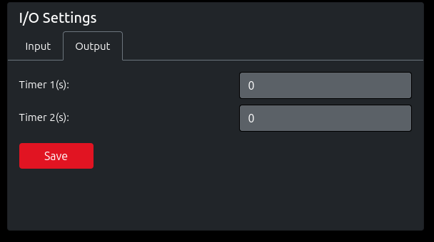
On the Settings page, the Output tab allows you to configure the timer durations for each relay — see Fig.4 Output Settings.
| Field | Description |
|---|---|
| Timer 1 (s) | The number of seconds Relay 1 (red light) stays ON after being triggered. Set to 0 to keep it ON indefinitely until a manual or remote command turns it OFF. |
| Timer 2 (s) | The number of seconds Relay 2 (horn) stays ON after being triggered. Set to 0 to keep it ON indefinitely until a manual or remote command turns it OFF. |
After changing the timer values, click Save to apply.
Remote Control via HTTP Commands
The built-in relays are controlled remotely by Metrici detection engines or Interface using HTTP requests. When a Metrici engine detects an event (e.g. an object crosses a line) or a condition is met in the Interface (such as a zone becoming full), it sends an HTTP command to the Horn Light device, which activates the corresponding relay.
| Command | URL |
|---|---|
| Turn Relay 1 (Red Light) ON | http://192.168.100.10/relay1/on |
| Turn Relay 1 (Red Light) OFF | http://192.168.100.10/relay1/off |
| Turn Relay 2 (Horn) ON | http://192.168.100.10/relay2/on |
| Turn Relay 2 (Horn) OFF | http://192.168.100.10/relay2/off |
Replace 192.168.100.10 with the actual IP address of your Horn Light device.
http://username:password@192.168.100.10/relay1/on. See the User Management chapter for details.
If the timer is set to a value greater than 0, the relay will automatically turn OFF after the specified duration — only the "ON" URL is needed in the detection engine. If the timer is set to 0, both ON and OFF URLs should be configured.
Integration with Metrici Detection Engines
The Metrici Horn Light is designed to work with Metrici detection engines and Metrici Interface. Metrici sends HTTP commands to the device's IP address to activate the relays. Below are examples showing how to configure this in the Metrici Control Panel for different engines.
Make sure the Area Counter or Line Counter engines are properly configured. You can find the documentations here:
Example — Area Counter
In the Metrici Control Panel, open the Area Counter engine settings. Under Engine Working Mode & External Trigger, enter the Horn Light device's IP in the signaling device fields:
| Field | Value | Effect |
|---|---|---|
| Signaling device URL (ON) | http://192.168.100.10/relay1/on | Activates the red light when the configured condition is met (e.g. a detection is made) |
| Signaling device URL (OFF) | http://192.168.100.10/relay1/off | Deactivates the red light when the condition clears |
Same settings are to be done in Metrici Interface in the appropiate menu such as alarms for LPR, for Area Counter or Line Counter etc. For example a zone or a location is almost full, a ceratin LPR detection was made and so on. To also trigger the horn, add a second signaling URL pointing to /relay2/on and /relay2/off.
4.3 Wiegand Settings
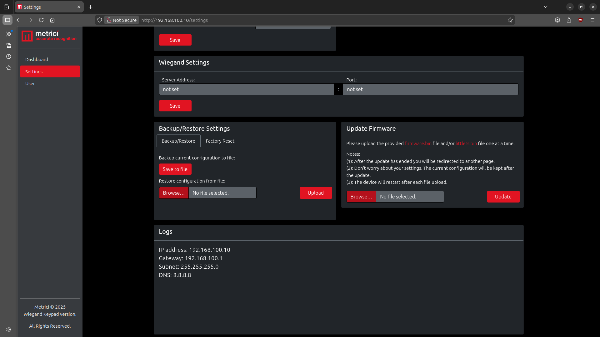
The Wiegand Settings section allows you to connect the Horn Light to a Wiegand server — see Fig.5 Wiegand & Other Settings. This is used in access control scenarios where a Wiegand reader communicates with a central server and the Horn Light acts as the alert output.
| Field | Description |
|---|---|
| Server Address | The IP address of the Wiegand server the device should communicate with. |
| Port | The port number used to connect to the Wiegand server. |
Click Save to apply. If not used, both fields display "not set".
4.4 Backup / Restore / Reset
Backup Current Configuration
Click Save to File to download a JSON file containing all current settings. This file can be used to restore settings later or deploy the same configuration to another device.
Restore Configuration
Click Browse, select a previously saved configuration file, then click Upload. The device will restart with the imported settings.
Factory Reset
Two reset options are available under the Factory Reset tab:
- Soft Reset — keeps the network settings (SSID, password, IP, gateway, subnet, DNS) but resets everything else (timers, input addresses, user credentials). The device restarts after the reset.
- Factory Reset — resets all settings to factory defaults. After restart, the device will be accessible at the default IP address:
192.168.100.10.
Both options require confirmation before executing.
4.5 Firmware Update
Firmware files (firmware.bin and littlefs.bin) are provided by Metrici and can be downloaded from support.metrici.ro.
To update:
- Download the firmware files from support.metrici.ro.
- Click Browse and select
firmware.bin. - Click Update.
- After the firmware update completes, repeat the process for the optional
littlefs.binfile.
5. User Management
The User page allows you to set a username and password for HTTP authentication — see Fig.6 User Settings. Only one user account can exist at a time — saving a new username or password will overwrite the previous one.
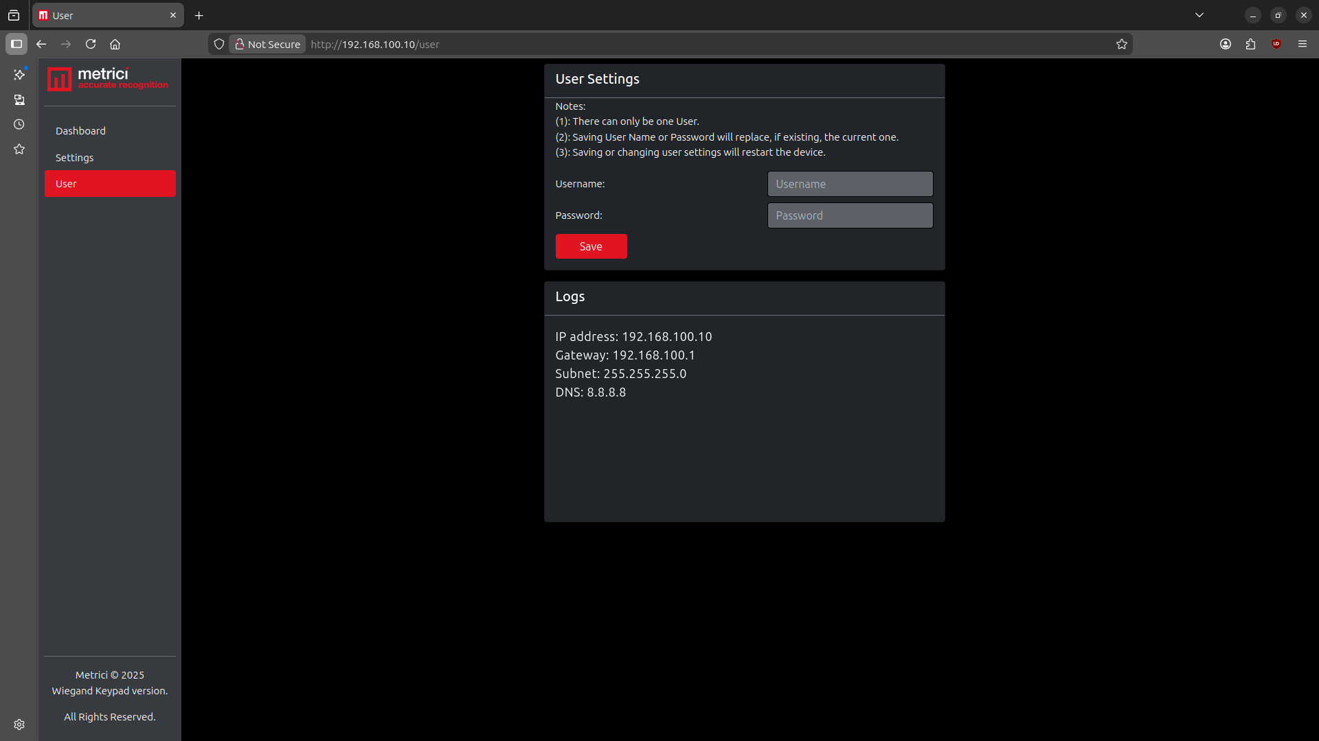
Setting a user is not mandatory for the device to work. It is a security feature that prevents unauthorized access to the web interface and HTTP commands from the local network.
http://username:password@192.168.100.10/relay1/on
6. Troubleshooting
Cannot access the web interface
- Verify that the device is powered on — check that the PoE switch or injector is providing power through the Ethernet cable.
- Make sure your computer or phone is on the same local network (same subnet) as the Horn Light device.
- Try accessing the default IP address:
http://192.168.100.10. - If you previously changed the IP or switched to DHCP, check your router's device list to find the current IP address.
- If all else fails, perform a factory reset to restore the default IP.
Red light or horn does not activate
- Go to the Dashboard > I/O Settings > Output tab and click On for Relay 1 or Relay 2 — verify the state changes and that the Logs section confirms the event.
- Check the physical wiring between the device and the light / horn.
- If using HTTP commands, verify the URL is correct and includes authentication credentials if a user is set.
Light or horn stays on and does not turn off automatically
- Check the timer value in Settings > I/O Settings > Output. If set to 0, the relay stays active indefinitely until it receives an explicit OFF command.
- Set the timer to a value greater than 0 (in seconds) if you want the output to turn off automatically after triggering.
HTTP commands not working
- Verify the IP address in the URL matches the device's current IP (check the Dashboard).
- If a user and password are set, make sure the URL includes credentials:
http://user:pass@IP/relay1/on. - Make sure the device is reachable from the machine sending the command (same network, no firewall blocking).
Device not receiving power
- Verify that your switch or injector supports PoE (IEEE 802.3af).
- Try a different Ethernet cable — damaged cables can prevent PoE power delivery.
- Try a different port on the PoE switch.
- If using a PoE injector, make sure it is plugged in and powered on.
Wiegand server not connecting
- Verify the Server Address and Port in Settings > Wiegand Settings are correct.
- Ensure the Wiegand server is running and reachable from the Horn Light's network.
- Check that no firewall is blocking the configured port.