Metrici MultiController
User Manual for End Users and System Administrators

Drag to rotate • Scroll to zoom • Right-click to move
Table of Contents
- Introduction
- How Does It Work
- First Boot
- Dashboard
- Settings
- Wiegand Settings
- Backup / Restore / Reset
- User Management
- Config File Format (Advanced)
- Troubleshooting
1. Introduction
The Metrici MultiController is a hardware product fully developed by Metrici. It is a multi-function LAN device designed to work both indoors and outdoors. The device can be wall-mounted or placed in a small space, and it acts as an input/output controller for a wide range of devices. It supports Ethernet connectivity with PoE (Power over Ethernet), can forward codes from a Wiegand keypad to a network server, and strengthens security and access control systems.
The controller features one Ethernet port (used for both power and network via PoE), two digital inputs, two digital outputs, and a 26-bit Wiegand interface. Its two inputs can be connected to inductive loops or sensors to send triggers to Metrici detection engines, while its two outputs can control up to two barriers, traffic lights, or any relay-driven hardware.
The Wiegand interface allows the MultiController to receive codes and forward them over the network to a configured server. This makes the device suitable for keypad-based access control, where a card can be validated against an external database or authentication service.
Technical Data
| Specification | Details |
|---|---|
| Description | Smart "all in one" LAN controller |
| Connectivity | 1 Ethernet port (PoE), 2 digital inputs, 2 relay-driven digital outputs, 1 Wiegand 26-bit interface |
| Characteristics | Web interface for setup and monitoring; can send triggers to 2 Metrici engines; can open 2 barriers; can convert each license plate number into a Wiegand ID by connecting to the Metrici database |
| Networking | Ethernet 10/100 Mbps |
| Protocols | HTTP over TCP/IP, RAW over UDP/IP, Wiegand 26-bit |
| Software Compatibility | Metrici v3.3 and higher |
| Power | PoE (IEEE 802.3af) via Ethernet cable — no separate power adapter needed |
| Operating Temperature | -20 to +50 °C, IP65 |
| Weight | 0.35 Kg (350g) |
Dimensions
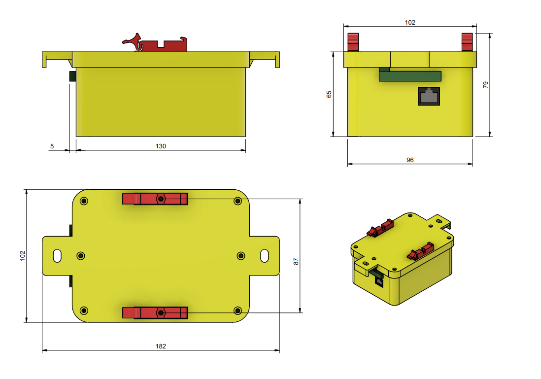
I/O Connector Pinout
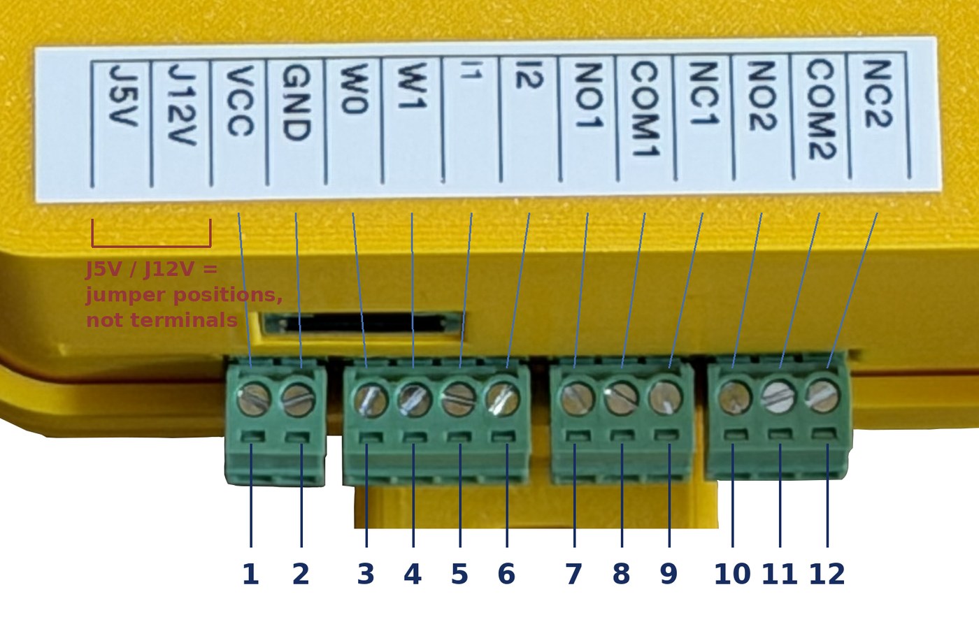
The MultiController's I/O terminal block has 12 terminals, numbered 1 to 12 from left to right when facing the connector. They are split across four pluggable screw connectors: terminals 1–2 are the power output and ground reference (VCC, GND), terminals 3–6 are the Wiegand data lines and digital inputs (W0, W1, I1, I2), terminals 7–9 are the Relay 1 contacts, and terminals 10–12 are the Relay 2 contacts. The same order is printed on the label on the enclosure, directly above the connectors.
| Pin | Label | Function |
|---|---|---|
| 1 | VCC |
Power output — 5V or 12V (selected by J5V/J12V jumper) |
| 2 | GND |
Ground (common reference for W0, W1, I1, I2) |
| 3 | W0 |
Wiegand Data 0 |
| 4 | W1 |
Wiegand Data 1 |
| 5 | I1 |
Digital Input 1 (trigger from loop/sensor) |
| 6 | I2 |
Digital Input 2 (trigger from loop/sensor) |
| 7 | NO1 |
Relay 1 — Normally Open contact |
| 8 | COM1 |
Relay 1 — Common contact |
| 9 | NC1 |
Relay 1 — Normally Closed contact |
| 10 | NO2 |
Relay 2 — Normally Open contact |
| 11 | COM2 |
Relay 2 — Common contact |
| 12 | NC2 |
Relay 2 — Normally Closed contact |
VCC outputs either 5V or 12V, selected by the J5V/J12V jumper. Set it before connecting a keypad or any other device to VCC.
Setting the jumper:
- Location — under the 2-way plug that holds terminals 1–2 (
VCC,GND). - Access — power the device down, then unplug that connector; the enclosure stays closed.
- Positions — left = 5V, right = 12V, the same left-to-right order as the label.
- Label markings — the
J5VandJ12Vcells mark these two positions; they are not screw terminals.
2. How Does It Work
The Metrici MultiController is designed to fit multiple working scenarios:
Scenario 1 — Trigger and Control
The MultiController is connected to two inductive loops or sensors to trigger Metrici detection engines when a vehicle arrives. In this scenario, it can also command up to two barriers, traffic lights, or other external hardware via its two digital outputs. It can be connected to visual or sound alarms as well.
Typical use cases include: controlling barriers when Metrici recognizes a license plate, triggering alarms on production lines when a faulty product is detected, or alerting security when people are detected in restricted areas on construction sites.
When communicating with the Metrici database, the MultiController receives commands to execute or deny actions for specific license plates. It can also switch a traffic light when a particular plate is detected.
Scenario 2 — Wiegand Keypad Input
The MultiController is used to collect codes from a 26-bit Wiegand. When a user swipes a card, the device receives the Wiegand frame over its W0/W1 lines and forwards the resulting code to a configured server address and port.
This setup is typically used for PIN-based access control: the forwarded code can be validated by a Metrici engine or any other authentication service, which then decides whether to grant access, open a barrier, or trigger a downstream action.
3. First Boot
The MultiController is powered via PoE (Power over Ethernet). Connect a single Ethernet cable from a PoE switch or PoE injector to the device's Ethernet port. This cable provides both network connectivity and electrical power — no separate power adapter is needed.
After connecting the Ethernet cable, open a browser on a computer connected to the same network and navigate to http://192.168.100.10 to access the web interface. The computer or phone used to access the dashboard must be connected to the same network (router) as the MultiController.
The MultiController interface has three main sections:
- Dashboard — displays the current status of the device
- Settings — where all configuration changes are made
- User — where a user account is created or edited
All settings have default values. They can be changed or left as they are. Please review the Backup/Restore chapter before making significant changes.
4. Dashboard
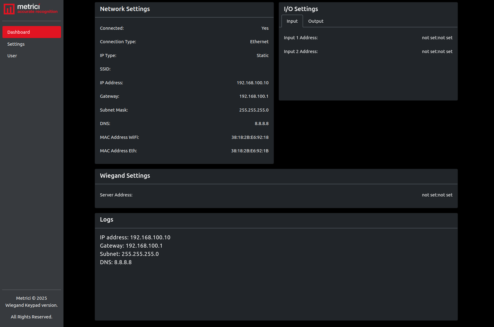
At the default IP address (192.168.100.10), the first page you will see is the Dashboard. It provides an instant overview of the device's current state, including network configuration, relay status, Wiegand settings, and activity logs.
Dashboard — Input Tab
The Input tab under I/O Settings shows the configured trigger addresses. Each input can be linked to a Metrici detection engine by setting an IP address and port number — see Fig.1 Dashboard – Input.
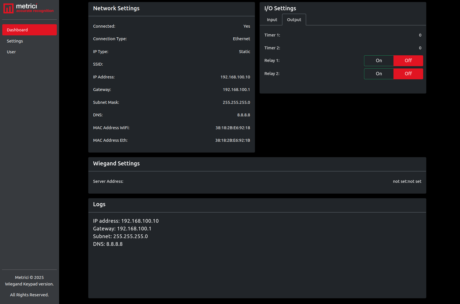
Dashboard — Output Tab
The Output tab displays the relay timer values and provides manual On/Off toggle buttons for Relay 1 and Relay 2. These buttons allow you to manually switch the relays for testing purposes — see Fig.2 Dashboard – Output.
The Dashboard also displays:
- Network Settings — connection status, IP type (Static/DHCP), IP address, gateway, subnet mask, DNS, and the Ethernet MAC address
- Wiegand Settings — the configured server address and port where Wiegand keypad codes will be forwarded
- Logs — a record of recent device activity including network configuration changes and relay state changes
5. Settings
To configure the MultiController, navigate to Settings in the left-side menu. Here you can change network settings, Wiegand settings, relay settings, perform backup and restore operations, and update the firmware.
Each settings field can be in one of three states:
- Unchanged — leave the field as it is, and the current value is kept
- "not set" — type this to reset the value to its default
- New value — enter a new value to replace the current one
5.1 Network Settings
The Network Settings tab allows you to change the local network configuration of the device. The MultiController connects over Ethernet, with either Static IP or DHCP addressing.
The device ships with factory defaults: IP Type: Static. This is why you can connect to it at the default address 192.168.100.10 using an Ethernet cable on first boot.
When any button or setting is active, it is displayed in red.
IP Type
Static IP allows you to manually enter the IP Address, Gateway, Subnet Mask, and DNS — see Fig.3 Settings – Network.
DHCP means the MultiController will automatically receive an IP address from the network router. All address fields become inactive and display "DHCP IP".
5.2 Relay Settings
The Relay Settings section contains two tabs: Input and Output.
Input (Triggers)
The MultiController can send trigger signals to up to two Metrici detection engines. For example, it can be connected to two inductive loops or sensors and instruct the detection engines to begin recognition when the sensors are activated — see Fig.4 Settings – Input.
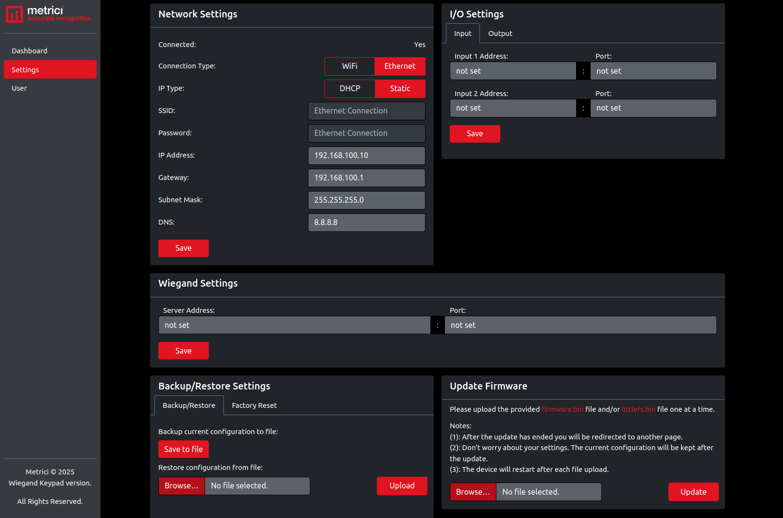
To configure the inputs:
- Input IP Address — the IP address of the Metrici server that will receive the trigger to begin detection
- Input Port — the unique port number for each detection engine, found in Metrici Control Panel. Port numbers begin at 3500 (the first engine uses 3500, the second uses 3501, and so on)
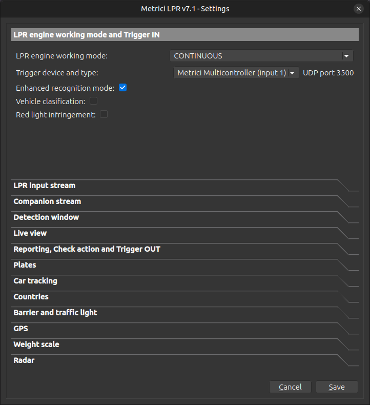
To set up the trigger on the Metrici server side:
- Open Metrici Control Panel on the detection server.
- Select the detection engine that should receive the trigger.
- Set it to Foreground with Watchdog working mode, press Edit when started.
- Navigate to Engine Working Mode and Trigger IN — see Fig.4.1 Working mode and Trigger IN.
- Change the engine working mode to "Started by TRIGGER".
- Under Trigger Device and Type, select Metrici MultiController (Input 1) or Metrici MultiController (Input 2) depending on which input provides the trigger.
- Metrici will automatically assign a port number (starting from 3500).
- Enter the server IP address and port number in the MultiController Input settings, then press Save.
Output (Relays)
In the Output tab, you can control the MultiController's two relays. Any device capable of receiving a relay command — such as barriers, traffic lights, doors, gates, alarms, or lights — can be connected and controlled — see Fig.3 Settings – Output.
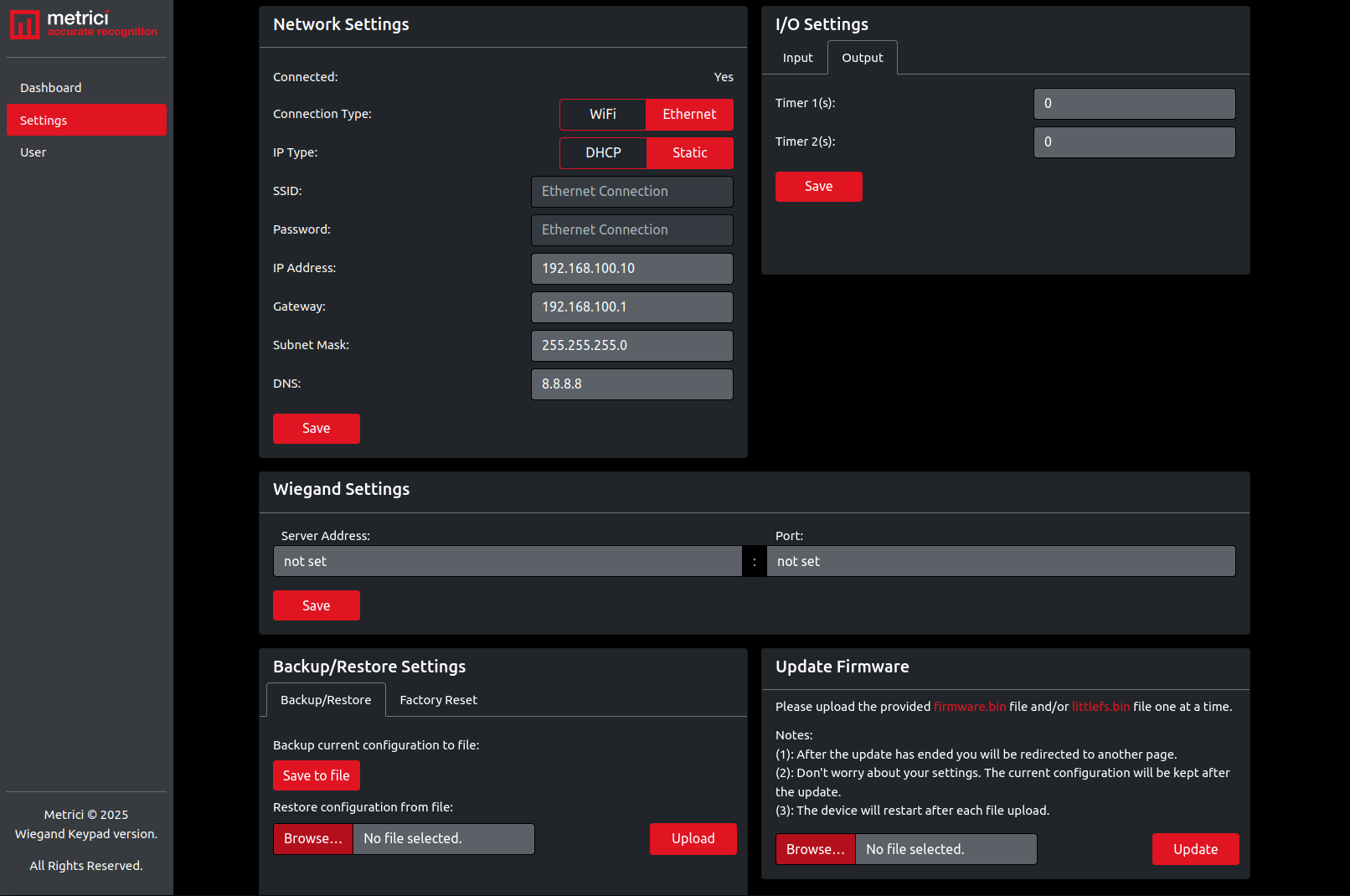
Timer 1 and Timer 2 define how long each relay stays ON (in seconds). Setting a timer to 0 means the relay will stay ON until it receives a manual or engine-driven command to turn OFF. This is recommended when both open and close commands will be sent from the Metrici detection engines.
The relays can be manually toggled from the Dashboard (Output tab) for testing. They can also be activated remotely from Metrici engines using HTTP commands:
| Command | URL |
|---|---|
| Open Relay 1 | http://192.168.100.10/relay1/on |
| Close Relay 1 | http://192.168.100.10/relay1/off |
| Open Relay 2 | http://192.168.100.10/relay2/on |
| Close Relay 2 | http://192.168.100.10/relay2/off |
For example, Relay 1 can be used for a barrier and Relay 2 for a traffic light. These URLs are entered in the Metrici Control Panel under Barrier and Traffic Light settings for the relevant detection engine.
If you are using the LPR engine, enter the IP addresses of the multi-controller relays in the input fields under the Barriers and Traffic Lights menu — see Fig. 3.1 Barriers and Traffic Lights.
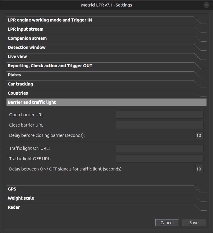
http://username:password@192.168.1.150/relay2/on. See the User Management chapter for details.
If the timer is set to a value greater than 0, the relay will automatically turn OFF after the specified duration. In this case, only the "Open" URL is required — the MultiController handles the closing automatically.
6. Wiegand Settings
The MultiController accepts input from a 26-bit Wiegand keypad connected to its W0/W1/GND lines. When a user enters a code, the device captures the Wiegand frame and forwards the resulting code as a RAW UDP packet to a configured server address and port. This allows the MultiController to act as a bridge between a physical Wiegand and a networked authentication service. Because the code is sent over UDP, the receiving server must be configured with a UDP listener on the matching port.
Setting Up Wiegand Communication
To activate Wiegand functionality, the following steps are required:
Step 1 — Physical Wiring
Connect three wires from the Wiegand keypad to the MultiController:
- W0 — Wiegand Data 0
- W1 — Wiegand Data 1
- GND — Ground
These connectors are located on the bottom of the device, next to the Ethernet port (green connectors).
Step 2 — Configure the MultiController
In the MultiController web interface, go to Settings → Wiegand Settings and enter:
- Server Address — the IP address of the server (typically the Metrici server) that will receive the codes captured
- Port — the port number on which the server is listening for incoming Wiegand codes
Press Save to store the configuration. If no server is configured, the Server Address and Port fields will display not set.
Step 3 — Set Up the Receiving Side
On the Metrici server, configure a trigger to receive the forwarded codes. Open the Metrici Control Panel, select the detection engine that should receive the Wiegand data, and configure it under Working Mode and Trigger IN by setting the Trigger device and type to Metrici MultiController RFID — see Fig.3.2 Wiegand Engine settings.
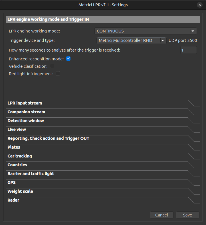
Once configured, each entry will be captured by the MultiController and delivered to the server for validation. The server then decides the resulting action — granting access, activating a relay, logging the event, or any other downstream behaviour.
7. Backup / Restore / Reset
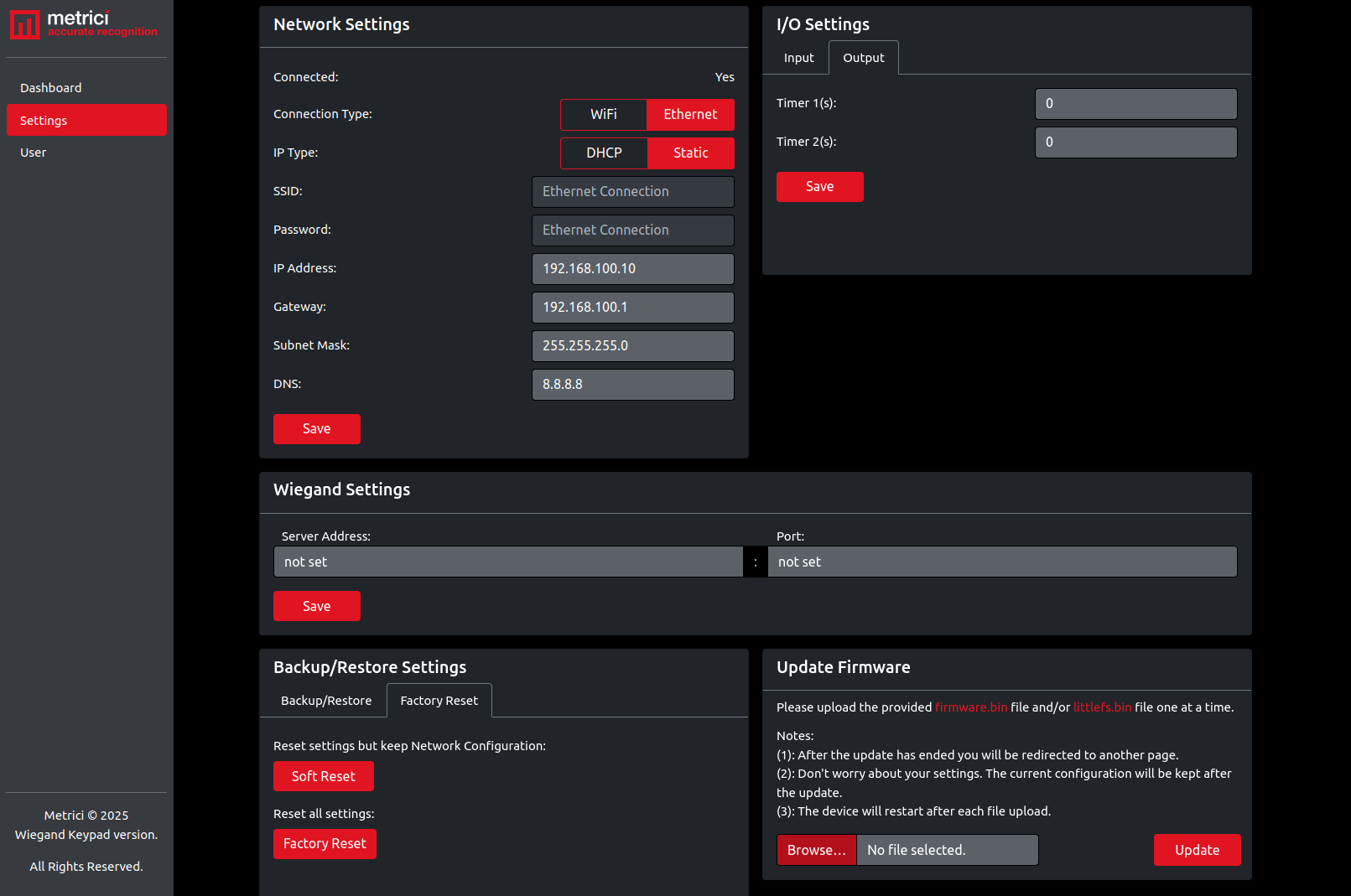
Backup Current Configuration
Click Save to File to download a JSON file containing all current MultiController settings. This file is named config.json and can be used to restore settings later or deploy the same configuration to another device — see Fig.5 Backup.
Restore Configuration
Click Choose File, select a previously saved config.json file, then click Upload. The device will restart with the imported settings. All current settings will be replaced by the contents of the uploaded file.
Factory Reset
Two reset options are available:
- Soft Reset — keeps the network settings (IP, gateway, subnet, DNS) but resets everything else (Input, Output, Wiegand). The device restarts after the reset.
- Factory Reset — resets all settings to their factory defaults. After restart, the device will be accessible at the standard IP address:
192.168.100.10.
Both options require confirmation before executing.
Firmware Update
Firmware files (firmware.bin and littlefs.bin) are provided by Metrici and can be downloaded from support.metrici.ro.
To update:
- Download the firmware files from support.metrici.ro.
- Click Choose File and select
firmware.bin. - Click Update.
- After the firmware update completes, repeat the process for the optional
littlefs.binfile.
Hard Factory Reset
The MultiController has a physical reset button inside the case, marked BUT1. This performs a complete factory reset, identical to the Factory Reset option in the web interface.
To perform a hard reset:
- Open the case lid and locate the button marked BUT1.
- Disconnect power from the device.
- Press and hold the button.
- While holding the button, reconnect power.
- Continue holding for 5–10 seconds, then release.
To verify the reset was successful, connect an Ethernet cable and try to access the device at http://192.168.100.10.
8. User Management
The User page allows you to set a username and password for HTTP authentication. Only one user account can exist at a time — saving a new username or password will overwrite the previous one — see Fig.6 User Settings.
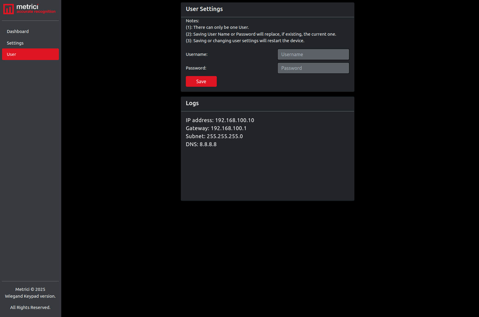
Setting a user is not mandatory for the MultiController to work. It is a security feature that prevents unauthorized access to the device's web interface from the local network.
http://username:[email protected]/relay1/onThis also applies to Wiegand URLs and any other API commands.
9. Configuration File Format (Advanced)
The MultiController configuration can be exported and imported as a JSON file named config.json. This is the only accepted file name — any other name will be ignored.
The configuration is divided into the following categories corresponding to the interface tabs:
network_settings
| Key | Accepted Values |
|---|---|
ip_type | Static or DHCP |
ip_address | IP address format (e.g., 192.168.100.10) |
gateway | IP address format |
subnet | IP address format (e.g., 255.255.255.0) |
dns | IP address format |
mac_address_eth | Read-only — cannot be modified |
input
| Key | Accepted Values |
|---|---|
ip_1 | IP address or not set |
port_1 | Number 1–65535 or not set |
ip_2 | IP address or not set |
port_2 | Number 1–65535 or not set |
output
| Key | Accepted Values |
|---|---|
timer1 | Number 0–99999 or not set |
timer2 | Number 0–99999 or not set |
relay1 / relay2
| Key | Accepted Values |
|---|---|
state1 / state2 | Off or On |
wiegand
| Key | Accepted Values |
|---|---|
server_address | IP address or not set |
port | Number 1–65535 or not set |
user
| Key | Accepted Values |
|---|---|
username | Alphanumeric string |
password | Alphanumeric string (minimum 8 characters) |
Example Configuration File
{
  "network_settings": {
    "ip_type": "Static",
    "mac_address_eth": "",
    "ip_address": "192.168.100.10",
    "gateway": "192.168.100.1",
    "subnet": "255.255.255.0",
    "dns": "8.8.8.8"
  },
  "input": {
    "ip_1": "not set",
    "port_1": "not set",
    "ip_2": "not set",
    "port_2": "not set"
  },
  "output": {
    "timer1": "0",
    "timer2": "0"
  },
  "relay1": {
    "state1": "Off"
  },
  "relay2": {
    "state2": "Off"
  },
  "wiegand": {
    "server_address": "not set",
    "port": "not set"
  },
  "user": {
    "username": "",
    "password": ""
  }
}10. Troubleshooting
Cannot access the web interface
- Verify that the device is powered on and connected to the network via Ethernet cable.
- Make sure your computer is on the same local network (same subnet) as the MultiController.
- Try accessing the default IP address:
http://192.168.100.10. - If you previously changed the IP or switched to DHCP, check your router's device list to find the current IP address.
- If all else fails, perform a hard factory reset (see Chapter 7) to restore the default IP.
Relay does not activate
- Verify the relay's power supply and physical wiring.
- Check the web interface Dashboard — the relay state should change when you click the On/Off button.
- If using HTTP commands, verify the URL is correct and includes authentication credentials if a user is set.
- Check the timer setting — if set to 0, the relay stays ON until it receives an explicit OFF command.
Wiegand keypad not sending codes
- Confirm the three wires (W0, W1, GND) are correctly connected between the Wiegand keypad and the MultiController.
- Verify the Server Address and Port in Wiegand Settings point to the correct Metrici server.
- The device only accepts standard 26-bit Wiegand; 34-bit or other formats will be rejected or misinterpreted.
- Check that the receiving service on the Metrici server is configured to listen on the matching port.
Triggers not reaching Metrici engines
- Verify the Input IP address and port number match the Metrici server settings.
- Confirm the detection engine is set to "Started by TRIGGER" mode with the correct MultiController input selected.
- Check that the Metrici server is reachable from the MultiController's network.
- Ensure the port number (starting from 3500) is not blocked by a firewall.
Device behaves unpredictably after configuration change
- Perform a Soft Reset to restore non-network settings to defaults while keeping your network configuration.
- If the issue persists, perform a Factory Reset and reconfigure from scratch.
- If you have a backup file, restore it after the reset.