Metrici Access Terminal
User Manual for End Users and System Administrators

Drag to rotate • Scroll to zoom • Right-click to move
Table of Contents
- 1. Introduction
- 2. Admin Menu
- 3. Network Settings
- 4. API Settings
- 5. QR Code Access & Parking Behavior
- 6. Barrier Control
- 7. Relay Control (GPIO23)
- 8. Input Sensor (GPIO24)
- 9. Relay & Input HTTP API
- 10. Security Settings
- 11. Language Settings
- 12. Admin Activity Logs
- 13. System Management
- 14. Physical Connectors
Introduction
The Metrici Access Terminal is an entry/exit device usually used to control parking barrier access. In parking scenarios if a LPR reading is missing for a parking access or any other type of access, a user scans a QR code (or enters an access code), the device validates it through the Metrici web application, and if approved, it opens the barrier — either through its built-in relay or by sending a command to an external controller.
It is an input/output terminal with a 7" display and a built-in camera for QR code scanning, with a built-in relay for barrier operation. It is powered over a single Ethernet cable (PoE 802.3bt), carries one input and one output (induction loop for vehicle presence on the input, barrier operation on the output for example), and ships with a wall/flat-surface or pole mounting bracket.
The device has two physical connections:
The full access flow works as follows:
Technical Data
| Specification | Details |
|---|---|
| Description | Input/output terminal with display and built-in camera for QR code scanning |
| Display | 7" touchscreen display |
| Connectivity | 1 Ethernet port (RJ45, Cat6A compatible) |
| Camera | 1 x 4 MP Camera for scanning QR codes |
| Networking | Ethernet 10/100 Mbps |
| Inputs / Outputs | 1 x IN (induction loop — vehicle presence), 1 x OUT (barrier operation) |
| Power | PoE 802.3bt via Ethernet cable — no separate power adapter needed |
| Software Compatibility | Metrici Web Application with LPR license (LPR and Parking for LPR) |
| Interface | User Interface plus Web based Dashboard for admins |
| Operating Temperature | -20 to +50 °C, IP55 |
| Mounting | Wall / flat-surface or pole mounting bracket (included) |
| Weight | 2.1 KG |
Dimensions
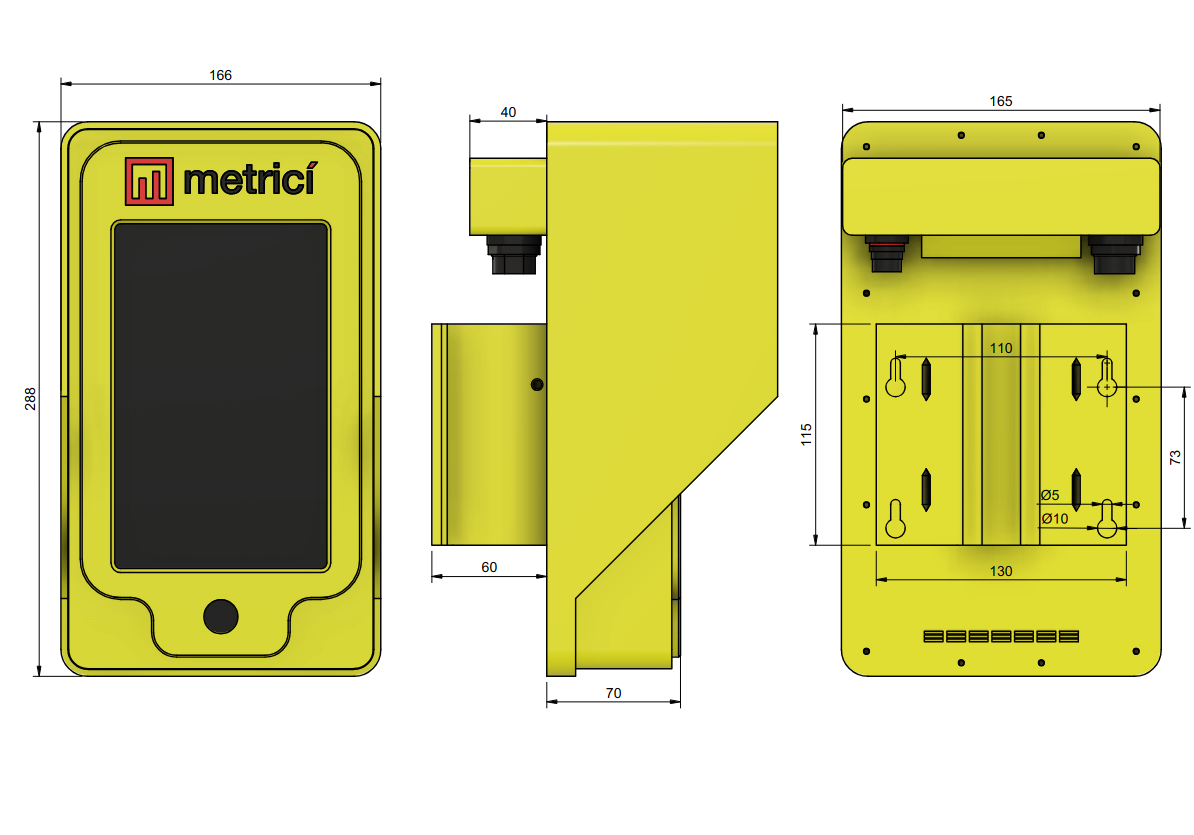
Power Supply (PoE 802.3bt)
The device is powered via PoE (Power over Ethernet), meaning it receives both network connectivity and electrical power through a single Ethernet cable. No separate power adapter is needed.
The terminal requires PoE 802.3bt. To power it correctly, the network switch or a PoE injector must support the 802.3bt standard. The Ethernet cable carries both data and 48V DC power, which the device converts to the voltages needed by its internal components.
Before You Begin — Web Application Setup
The Access Terminal does not work on its own. It validates the QR codes drivers present against the Metrici web application/ Interface and reports each entry/exit event back to it. Before you configure the terminal's 4. API Settings or create any QR codes, the web application must already be set up — create a location in the Interface, add cameras with and activate the relevant modules (Metrici LPR basic and, for parking, Parking for LPR module) which you will configure.
If the Metrici Interface is not set up yet, follow these manuals first to configure the needed parameters for the terminal:
- Metrici Web Interface — login, Global Settings, and Locations & Cameras (the base setup every module needs).
- License Plate Recognition (LPR) — the license plate recognition module.
- Parking Module for LPR — parking management, including tenants and visitor access codes.
- Parking Place Detector (PPD) — monitors individual parking spaces for occupancy (free / busy).
Admin Menu
The terminal's interface can be reached in two ways: directly on the device's touchscreen, or from a web browser on the same network by entering the device's IP address.
192.168.100.121. Open http://192.168.100.121 in a browser on the same network. If
the dashboard does not load at that address, the terminal may be using a different IP — look it up in the
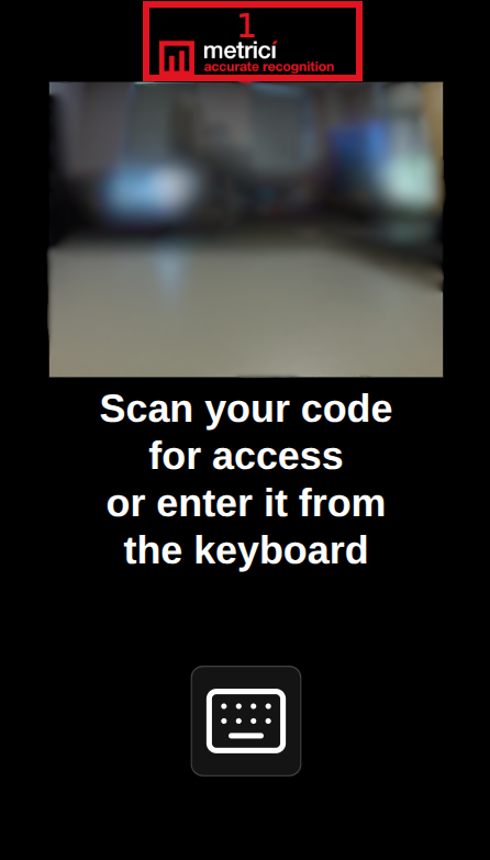
device's network settings (see the live configuration in Fig.2 Live Configuration (1)) or ask your network administrator.To open the admin login — on the physical terminal or in the web interface — tap the Metrici logo at the top of the screen 8 times — vezi Fig.A Firmware Interface (1) .
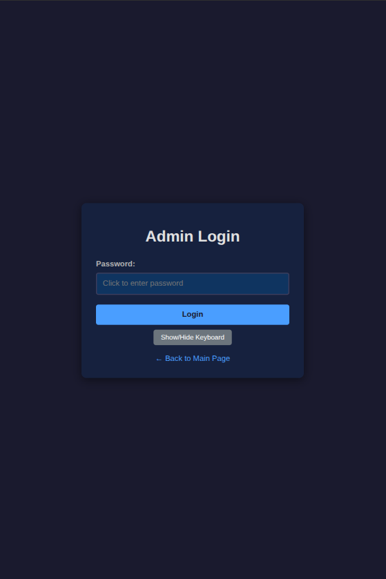
After tapping the logo 8 times or connected via http, a login page opens. The default password is "metriciadmin" — see Fig.1 Admin Login.
After the first login, we recommend changing the password (see 10. Security Settings).
Network Settings
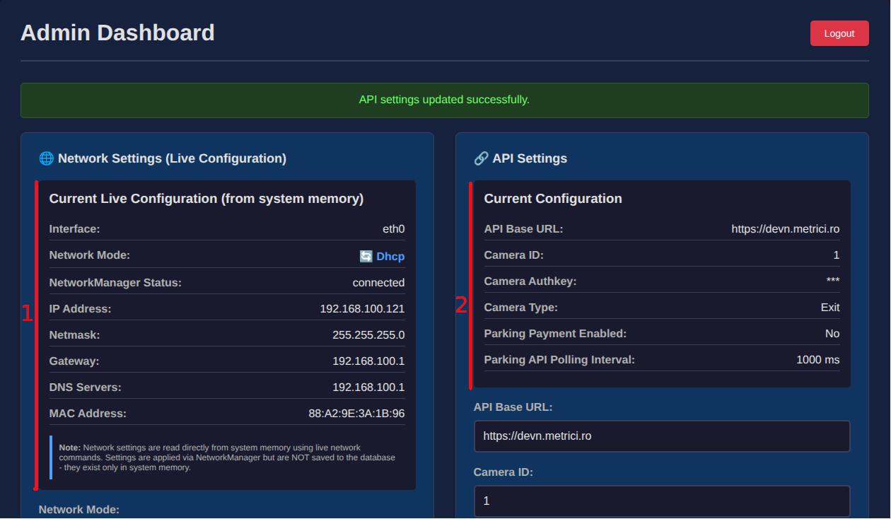
Configures the device's network connection. The top section of the dashboard shows the current live configuration read from system memory — see Fig.2 Live Configuration (1).
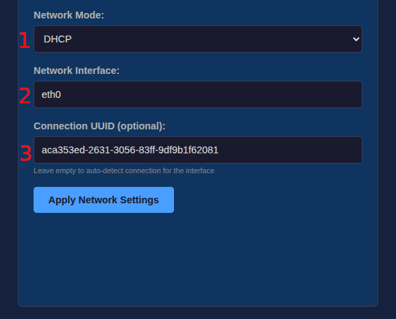
The bottom section allows you to change the settings and apply them — see Fig.3 Network Configuration.
These settings must be configured during installation to match the local network at the parking location. The installer needs to obtain the correct values from the network administrator or router configuration.
Network Mode
In DHCP mode, the device gets an IP automatically from the router — see Fig.3 Network Configuration (1). In Static IP mode, you manually assign all fields below — see Fig.4 Static Network Configuration (1). Static IP is recommended so the device always has the same address.
Network Interface
Enter: eth0 — see Fig.3
Network Configuration (2). This is the name of the Ethernet port on the device. Since
the terminal connects via a single Ethernet cable (PoE), this value should always remain
eth0.
Connection UUID (optional)
The NetworkManager connection identifier (UUID) for the interface — see Fig.3 Network Configuration (3). Leave it empty to auto-detect the connection for the chosen interface. In most installations this can be left blank.
IP Address
The device's unique address on the local network. This is how you access the admin dashboard from a browser. It must be unique — no other device on the same network can use the same IP — see Fig.4 Static Network Configuration (4).
e.g. 192.168.100.121
Netmask
Defines which IP addresses are on the same local network. With 255.255.255.0 the device can reach
any address from 192.168.100.1 to 192.168.100.254 directly. In most cases this value stays as
255.255.255.0 — see Fig.4 Static Network
Configuration (5).
Gateway
The IP address of the router. The device uses this to reach the internet — specifically the Metrici API server. If this is wrong, QR code validation will fail because the device cannot connect to the API — see Fig.4 Static Network Configuration (6).
e.g. 192.168.100.1
DNS Server
Translates domain names (like devn.metrici.ro) into IP addresses. Usually set to the same address as the gateway (the router handles DNS). Without a working DNS, the device cannot find the API server by name — see Fig.4 Static Network Configuration (7).
e.g. 192.168.100.1
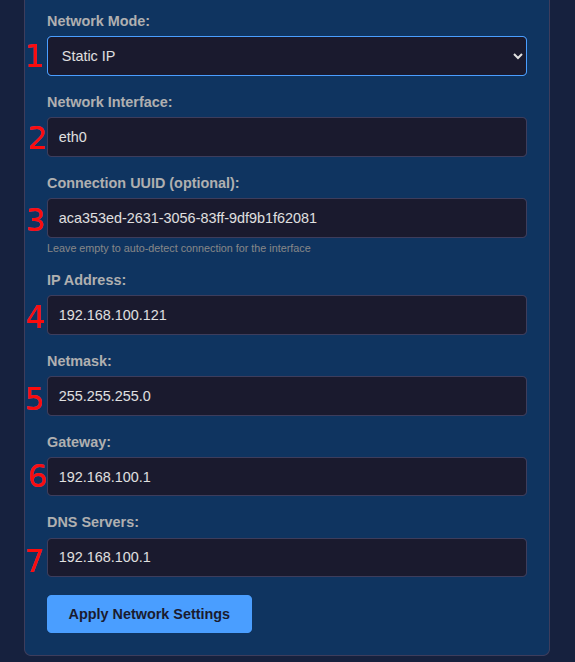
After configuring the network settings, the user can access the admin dashboard from a browser by entering the IP address that was set at — see Fig.4 Static Network Configuration (4).
API Settings
Controls how the device communicates with the Metrici server. When a QR code is scanned, the device sends the data to this API for validation. The server responds whether to grant or deny access. The top of the API panel shows the current live configuration — see Fig.2 Live Configuration (2).
Before we can make the API settings, we need to add a camera into the web application:
- First, the camera must be configured in the LPR engine and fully operational before proceeding. You can find the documentation here: License Plate Recognition.
- Second, follow the instructions in the Locations & Cameras section of the Web Interface manual. The camera type must be License Plate Recognition - Parking or License Plate Recognition - Default.
API Base URL
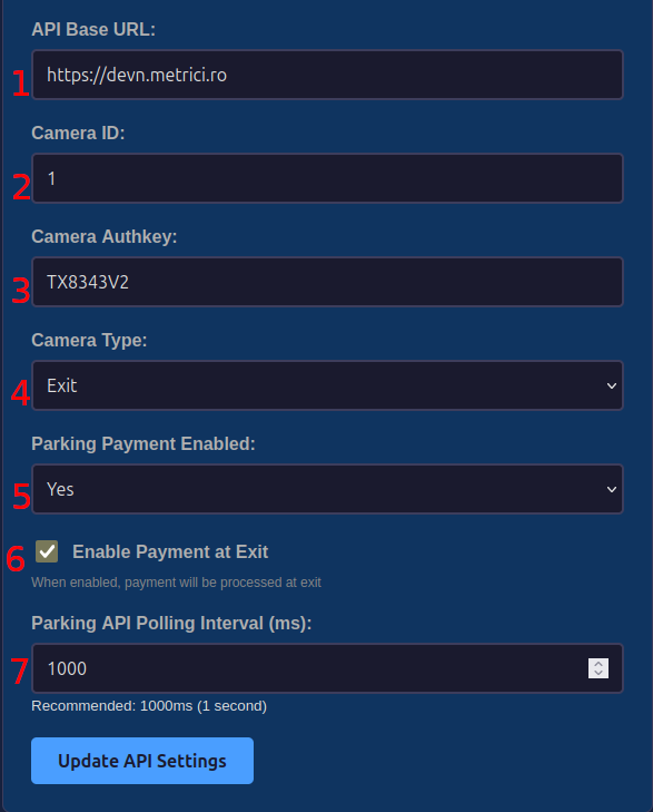
The base URL must point to the server where the Metrici web application is running — see Fig.5 API Configuration (1). Enter only the scheme and host (the device appends the required API paths automatically):
Examples:
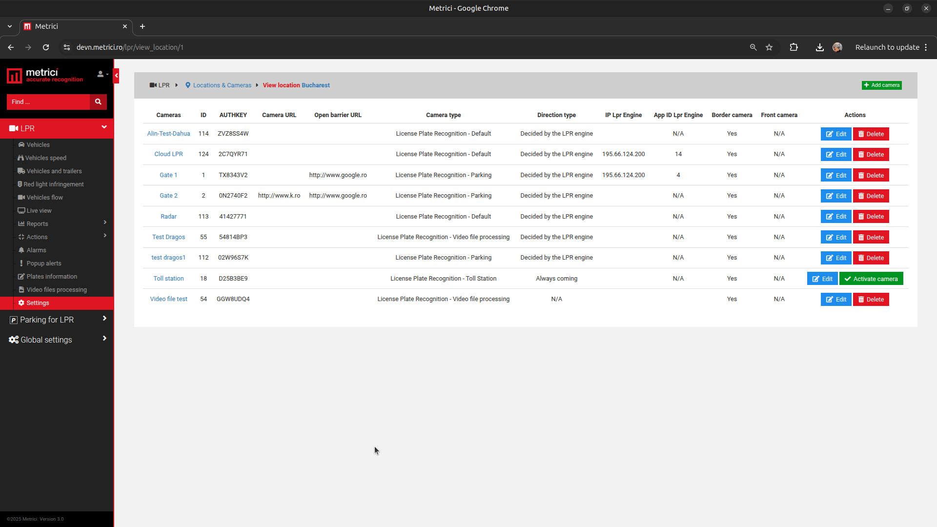
This ID is assigned by the Metrici web application when registering a new camera — see Fig.5 API Configuration (2). You can see where to find the ID in Fig.6 ID & Authkey. Namely, in Metrici Interface in Settings, Location and Cameras. Choose location and see cameras assigned to it. Find the appropiate one
This is generated by the Metrici web application and must match the key registered for this Camera ID — see Fig.5 API Configuration (3). You can see where to find the authkey in Fig.6 ID & Authkey.
Tells the Metrici web application in which direction the event was registered — whether this device controls an Entry point or an Exit point of the parking area — see Fig.5 API Configuration (4).
Allows parking payments at the terminal — see Fig.5 API Configuration (5). Set it to Yes to allow payments, or leave it as No if your installation does not use Metrici parking payments.
This checkbox works together with Parking Payment Enabled. When Parking Payment Enabled is set to Yes, drivers must pay the parking fee before they can leave the parking. The payment can be made in two ways — at this terminal or at a separate Metrici Payment Terminal — and this checkbox controls whether this terminal offers payment — see Fig.5 API Configuration (6):
- Checked — the payment method on this terminal is activated (payment menus, the Payment Required QR, etc. — see the payment flow in 5. QR Code Access & Parking Behavior). Drivers can make the payment both at this terminal and at a Metrici Payment Terminal — if the location provides one.
- Unchecked — this terminal does not process payments. If Parking Payment Enabled is still set to Yes, drivers must make the payment at a Metrici Payment Terminal and then present the paid ticket at this exit terminal to open the barrier.
The terminal makes a request to the parking (web application) once per interval to receive events from parking — see Fig.5 API Configuration (7). The recommended value is 1000 ms (1 second) — one request per second.
QR Code Access & Parking Behavior
The QR codes (and access codes) that drivers present at the terminal are generated in the Metrici web application. This terminal works with LPR and Parking for LPR, and there are two ways to create them: through the Action List or through Tenants. Both produce a QR code and an access code that the terminal accepts. How the terminal behaves on a scan also depends on its Camera Type (Entry or Exit) and whether Parking Payment Enabled is set — both configured in 4. API Settings and described in the parking-behavior sections below.
1. Action List (LPR)
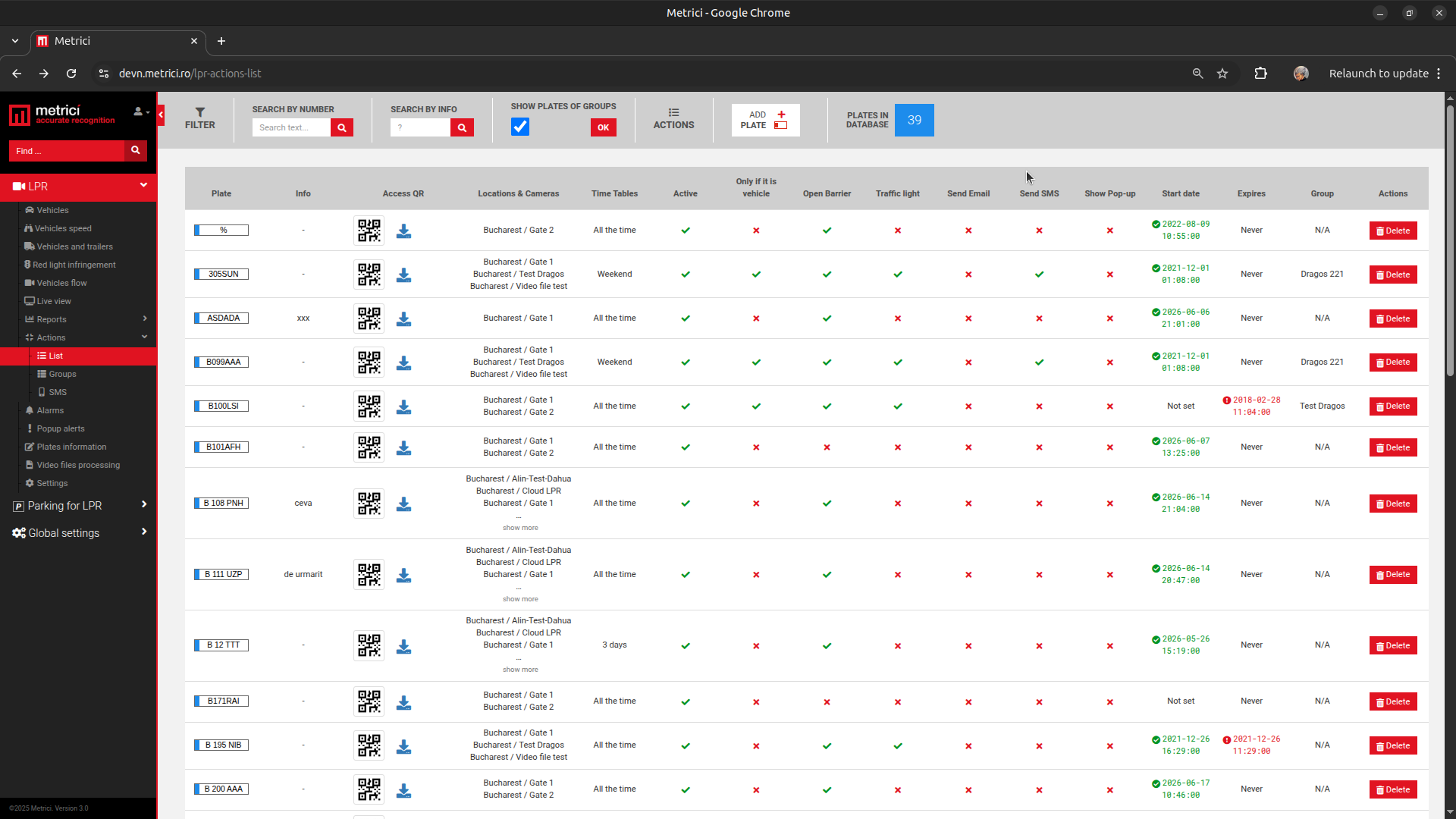
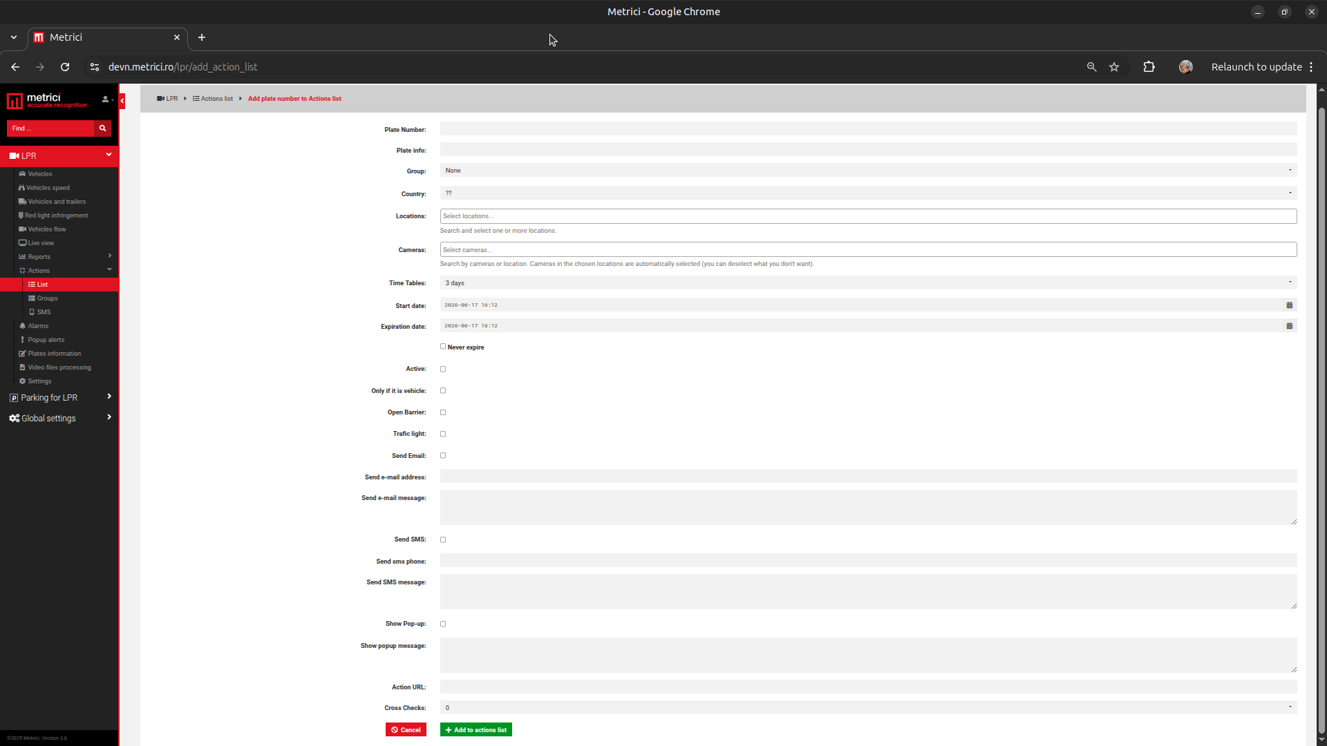
In the Metrici web application, go to LPR → Actions → List to open the action list — see Fig.7 Action List. Click ADD PLATE and fill in the plate number and the rest of the form — see Fig.8 Add Plate to Action List.
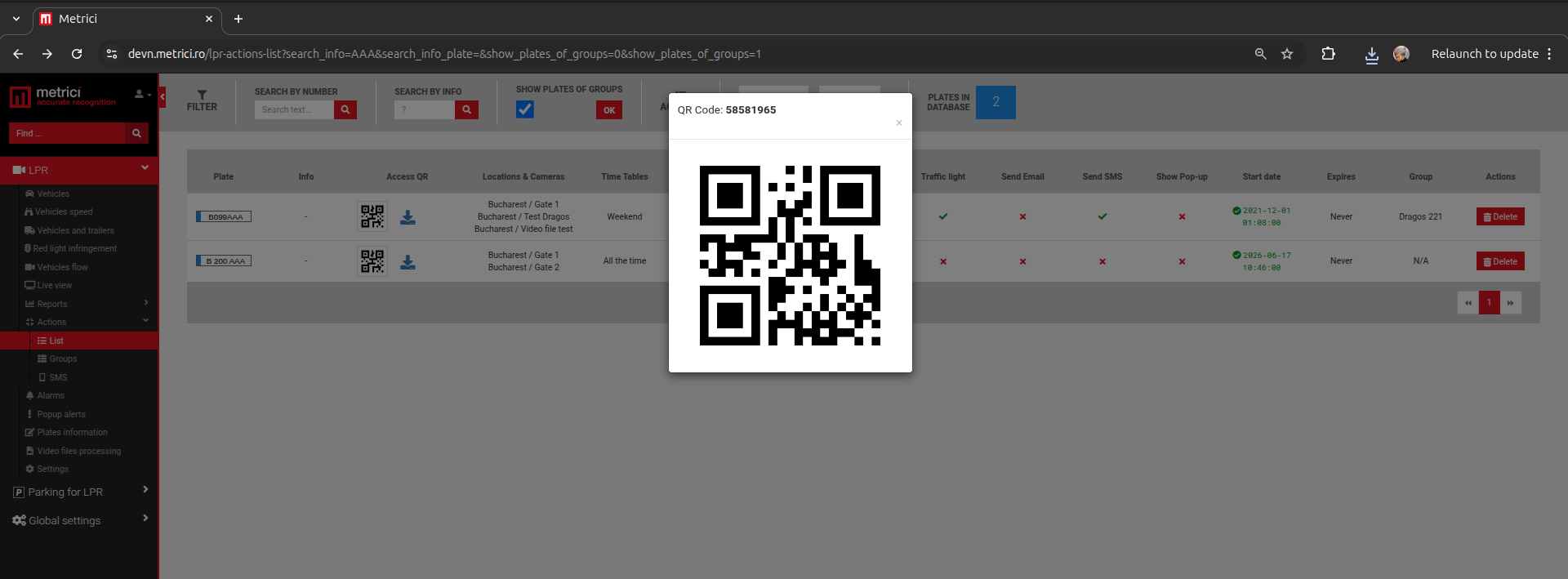
After the plate is added, an Access QR code and an access code are created for it. You can
view and download the QR from the Access QR column of the action list — see Fig.9 Access QR Code. The number shown
above the QR (for example 58581965) is the access code, which can be entered manually when
scanning is not possible.
2. Tenants (Parking for LPR)
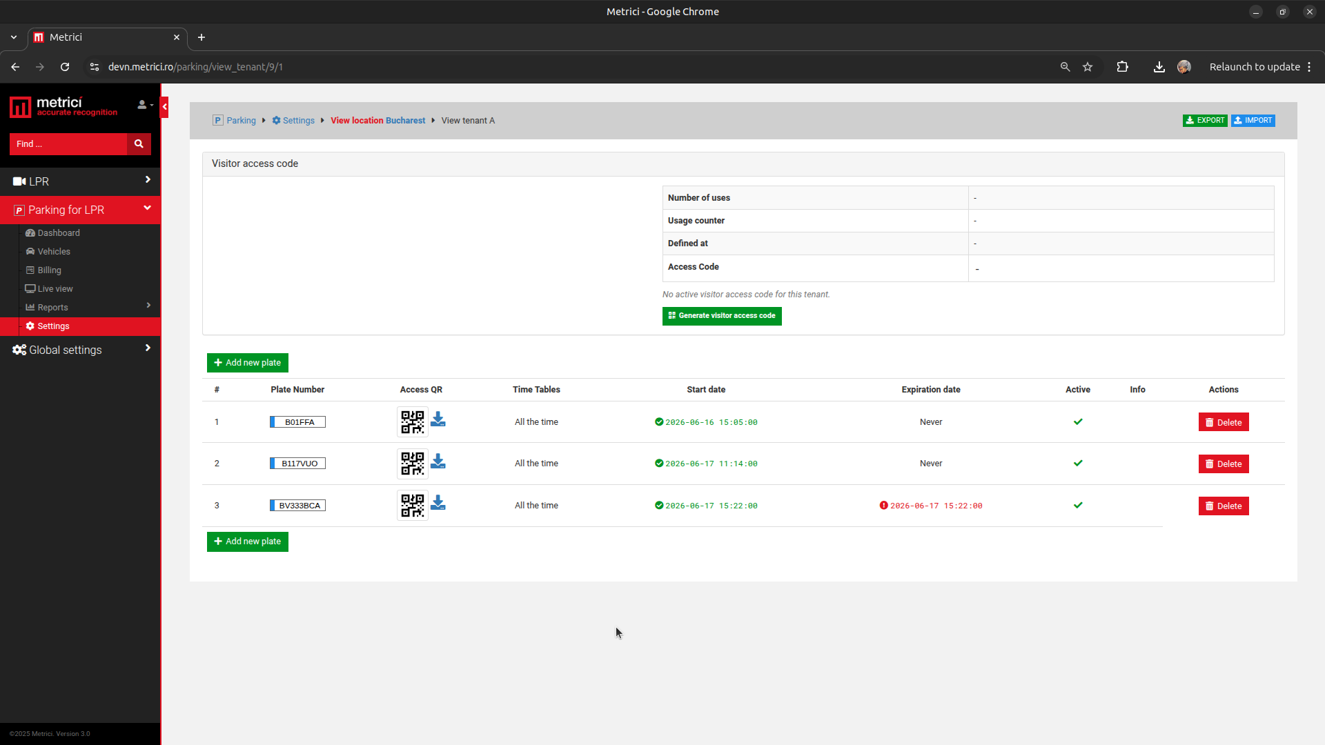
A QR code is also created when you add a plate to a tenant. In the web application, go to Parking for LPR → Settings, open the location and the tenant, then use Add new plate. Each plate added to the tenant gets its own Access QR in the Access QR column — see Fig.10 Tenant Plates & QR. You can also use Generate visitor access code to issue a temporary visitor QR / access code for that tenant.
What the Driver Sees: Access Granted or Rejected
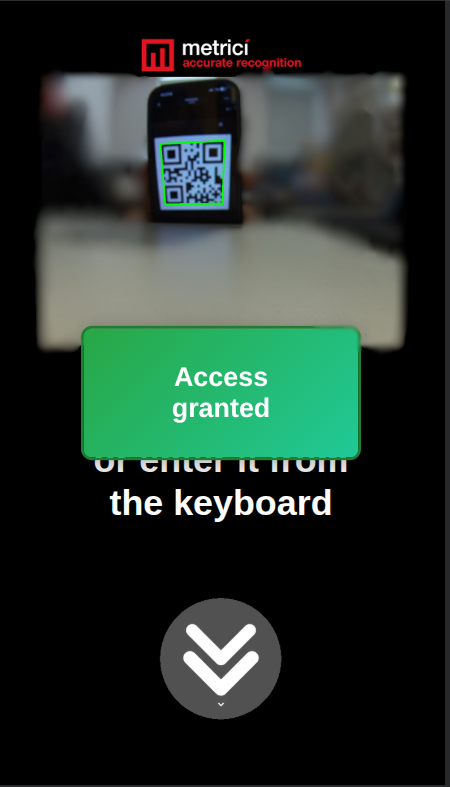
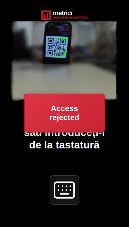
When a valid QR code is scanned — or its access code is typed on the on-screen keyboard — the terminal shows a green Access granted message and opens the barrier — see Fig.11 Access Granted. If the code is invalid, expired, or access cannot be granted, it shows a red Access rejected message and the barrier stays closed — see Fig.12 Access Rejected.
Access Requires a Free Parking Space
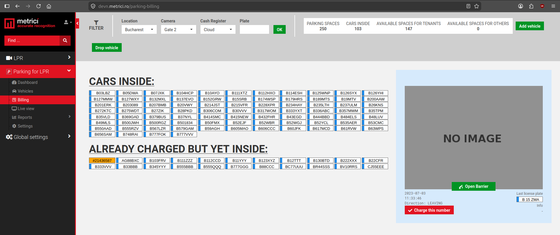
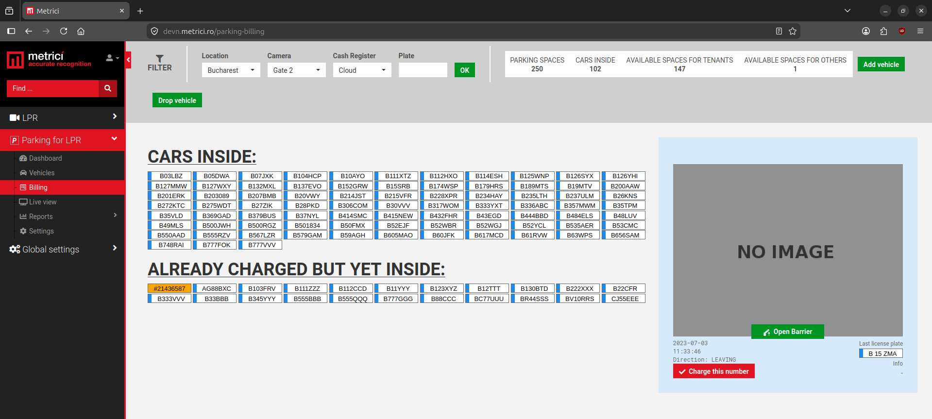
A valid QR code or access code is not enough on its own — the parking must also have room. The Billing page in Metrici Interface, Parking module shows live counters at the top right: total Parking Spaces, Cars Inside, Available Spaces for Tenants, and Available Spaces for Others.
If Available Spaces for Others is 0, the lot is full for general (non-tenant) access and the terminal rejects the scan even when the code is valid — see Fig.13 (0 available), which produces Fig.12 Access Rejected. As soon as a space frees up — for example a car exits and the counter shows 1 — the next scan is granted and the barrier opens — see Fig.14 (1 available) and Fig.11 Access Granted. Same scenario applies even for tenants if they have O places left in the parking, as the tenant for example can have a certain number of places available, but multiple vehicle access. If all theirs places are occupied, the access is rejected.
Tenants: Preserve Tenant Spaces (Important)
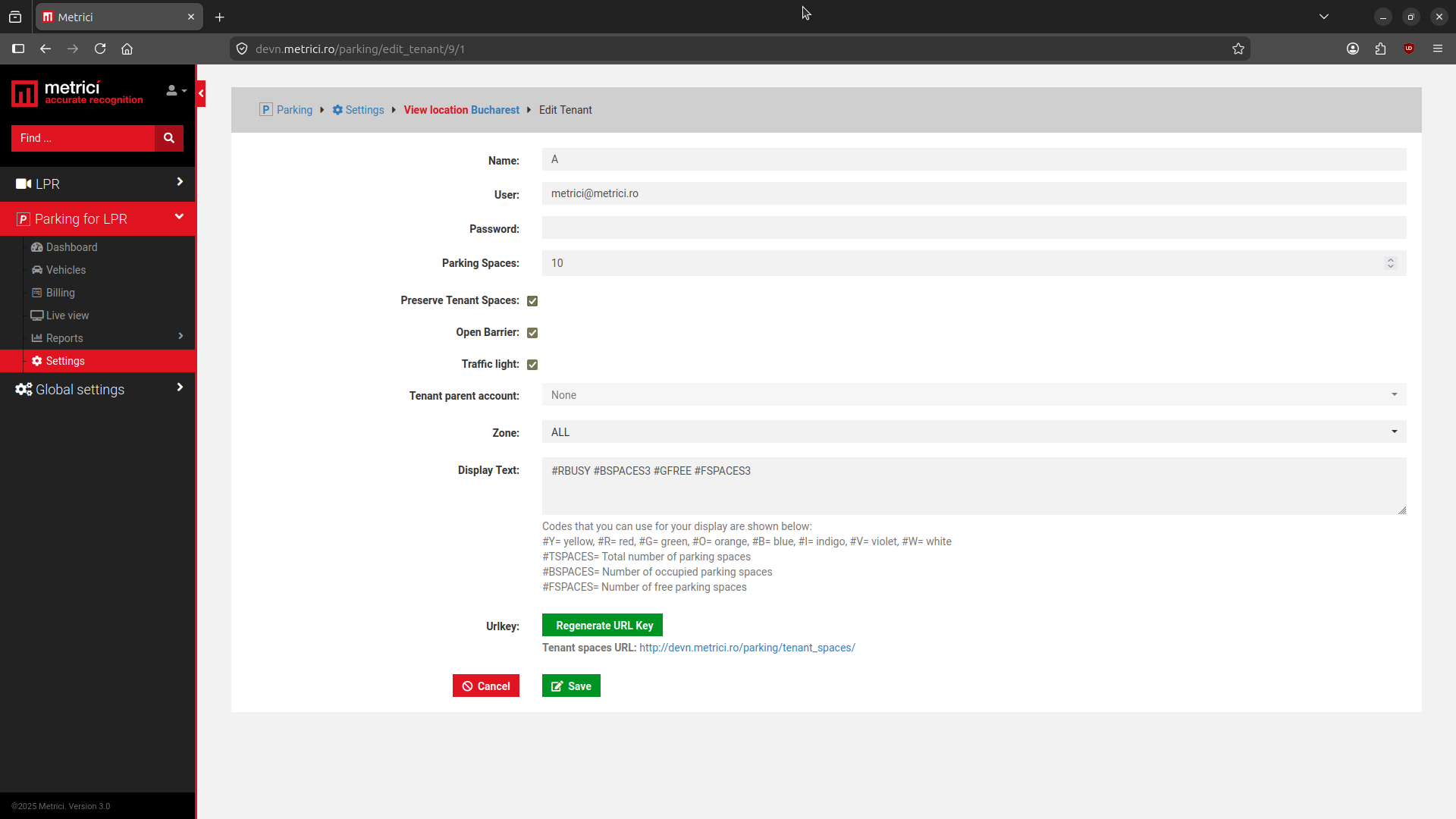
Tenants can have their own reserved spaces, shown as Available Spaces for Tenants on the Billing page — but only if the tenant is set to have a reserve option. When creating or editing a tenant (Parking for LPR → Settings → Edit Tenant), enable Preserve Tenant Spaces — see Fig.15 Preserve Tenant Spaces.
Entry and Exit — Without Payment (Parking Payment Enabled = No)
When Parking Payment Enabled is set to No, the terminal simply grants or denies access from the scanned QR code or access code. What a granted scan does to the parking depends on the terminal's Camera Type:
- Entry — the plate is added to the parking lot. It then appears in the Metrici web application under Parking for LPR → Billing, in the Cars Inside list — see Fig.13 Billing.
- Exit — the plate is removed from the parking lot and disappears from the Cars Inside list in Billing.
Entry and Exit — With Payment (Parking Payment Enabled = Yes)
If the parking operator charges for access, set Parking Payment Enabled to Yes. The flow then differs depending on the terminal's Camera Type.
At Entry (Camera Type = Entrance)
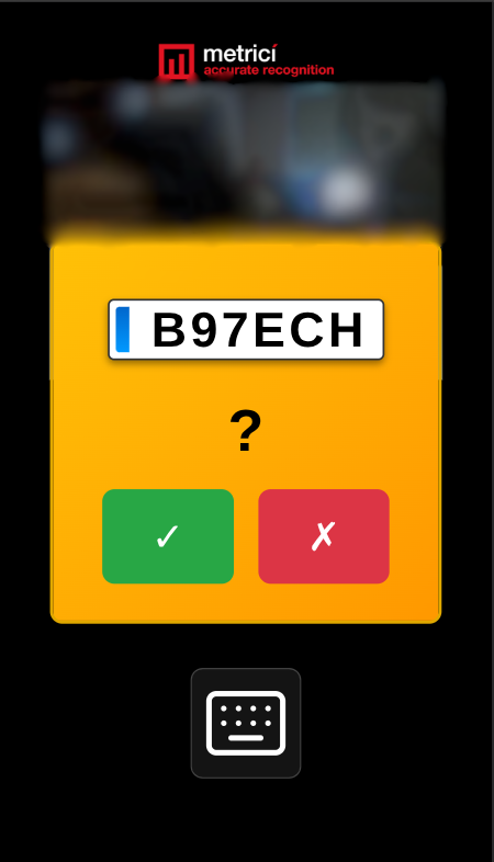
When the LPR camera detects a vehicle, the terminal shows the recognized plate and asks whether it is correct — see Fig.16 Plate Confirmation.
- If the driver taps the green ✓, the barrier opens and the plate is stored in the database, where it appears in Parking for LPR → Billing. (This is visible to the parking owner or administrator only — regular drivers never see the web application.)
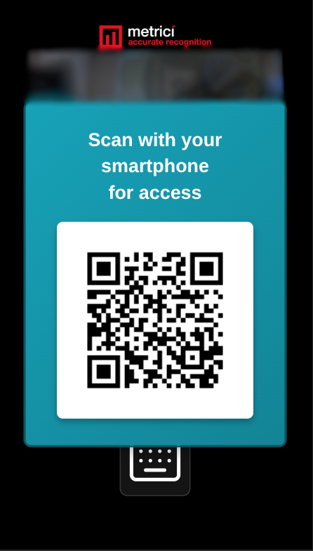
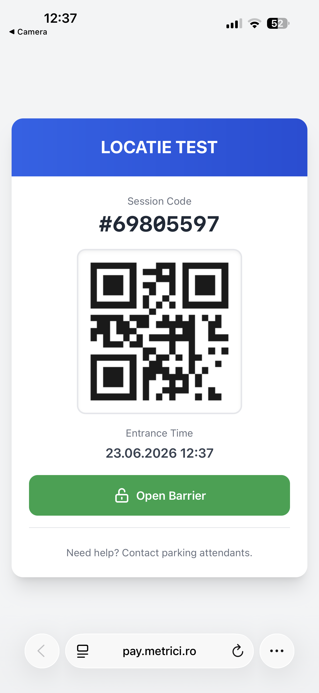
- If the plate is wrong, the driver taps the red ✗, and a QR code appears on the terminal screen — see Fig.17 Scan for Access. Scanning it with a phone opens a page that creates a session code with its own QR and an Open Barrier button — see Fig.18 Session Code.
This session code replaces the license plate and is stored in the database- it is in fact similar to a phisical parking ticket. It identifies the parking session and is used to pay at exit. This is the reason this code must be saved in phone. The same session code can also be entered in a Metrici Payment Terminal instead of a license plate — see the plate / code input section of the Metrici Payment Terminal manual.
At Exit (Camera Type = Exit)
An exit terminal can also collect the parking fee, so the driver pays and leaves in a single stop. Two settings in 4. API Settings must be turned on:
- Parking Payment Enabled — set to Yes
- Enable Payment at Exit — checked
With both in place, the driver goes through the following steps:
- The driver scans a QR code at the terminal — either one from the Action List, or the session code received at entry.
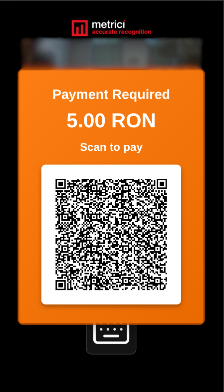
- The terminal shows the amount due as a Payment Required QR code — see Fig.19 Payment Required.
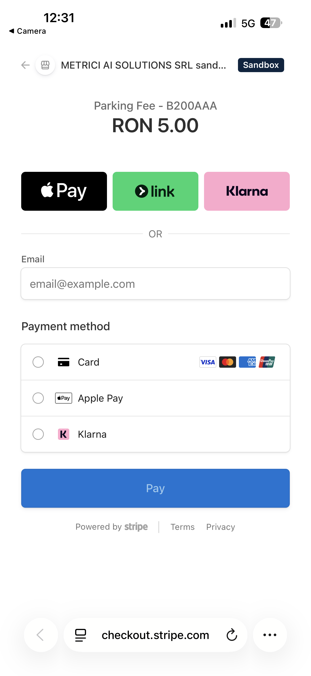
- The driver scans that QR code with a phone. This opens the Stripe checkout page, where the parking fee is paid — see Fig.20 Stripe Checkout.
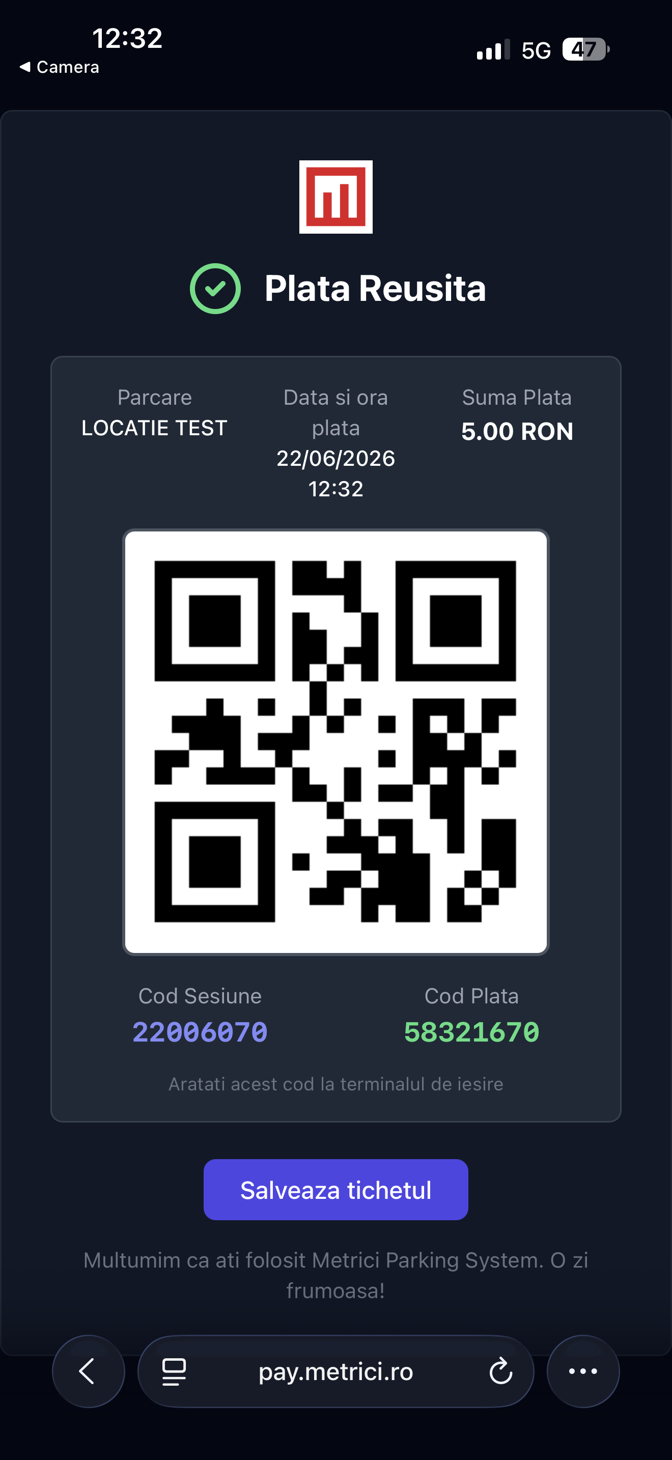
- After the payment is processed and validated the phone shows a ticket containing a QR code, a session code, and a payment code — see Fig.21 Payment Successful.
- The driver scans that ticket at the same terminal, and the barrier opens.
Barrier Control
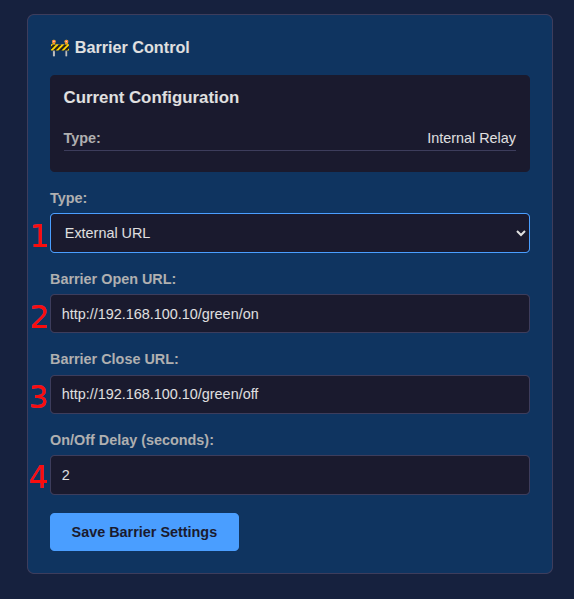
Barrier Control selects how the terminal opens the barrier. The top of the card shows the current configuration, and the Type selector lets you choose between two modes.
Internal Relay
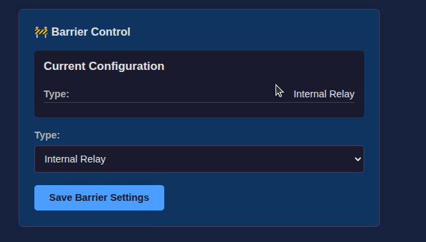
In Internal Relay mode, the terminal opens the barrier through its onboard relay (GPIO23), which physically closes a circuit to the barrier — see Fig.22 Barrier Control – Internal Relay. The relay's behaviour is configured in 7. Relay Control (GPIO23).
External URL
In External URL mode, the terminal does not switch its onboard relay. Instead, it sends HTTP requests to an external device — for example a Metrici Multicontroller — which then operates the barrier. This is useful when the barrier is wired to a separate controller or relay board rather than directly to the terminal.
| Field | Description |
|---|---|
| Type | Set to External URL — see Fig.23 Barrier Control – External URL (1). |
| Barrier Open URL | The HTTP address the terminal calls to open the barrier, e.g.
http://192.168.100.10/green/on — see Fig.23 Barrier Control – External URL
(2). |
| Barrier Close URL | The HTTP address the terminal calls to close the barrier, e.g.
http://192.168.100.10/green/off — see Fig.23 Barrier Control – External URL
(3). |
| On/Off Delay (seconds) | How long to wait between the open call and the close call — see Fig.23 Barrier Control – External URL
(4). With a value of 2, the terminal calls the open URL, waits 2
seconds, then calls the close URL. |
Relay Control (GPIO23)
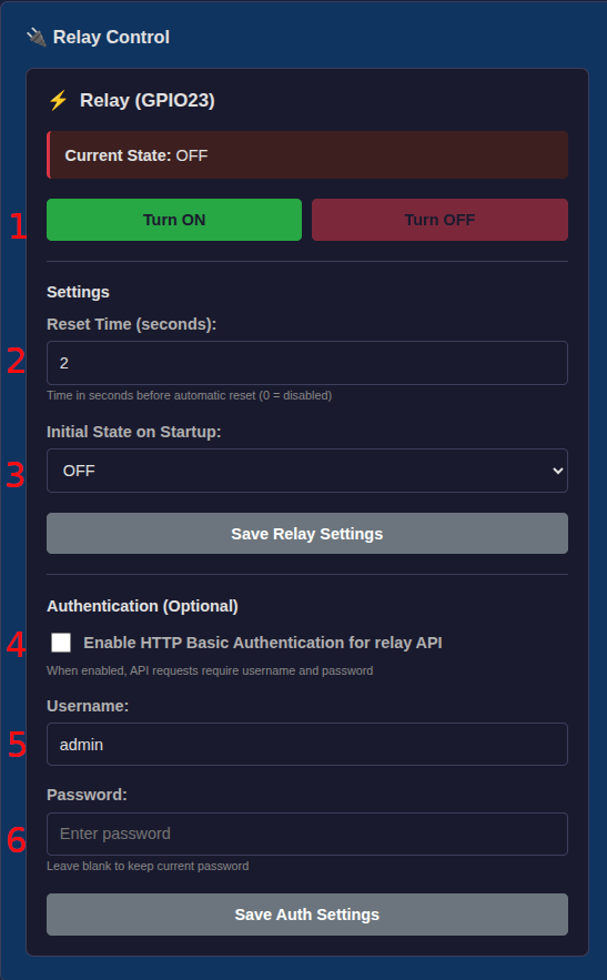
The relay is the device's output when Internal Relay mode is selected (see 6. Barrier Control). It acts as an electrical switch that sends an "open" signal to the parking barrier. When activated, the relay closes a circuit for a set amount of time, which the barrier interprets as an open command.
| Field | Description |
|---|---|
| Turn ON / Turn OFF | Manual relay control — see Fig.24 Relay Control (1). |
| Reset Time | Seconds before the relay auto-closes (0 = disabled) — see Fig.24 Relay Control (2). |
| Initial State on Startup | Choose whether the relay starts in the ON or OFF state when the device boots — see Fig.24 Relay Control (3). |
Authentication (Optional)
The relay can also be controlled over HTTP through the device's API (see 9. Relay & Input HTTP API). To protect this API, you can enable HTTP Basic Authentication.
Tick Enable HTTP Basic Authentication for relay API — see Fig.24 Relay Control (4) — then set a Username — see Fig.24 Relay Control (5) — and a Password — see Fig.24 Relay Control (6). When enabled, requests to the relay API must include these credentials. Leave the password field blank to keep the current password.
Input Sensor (GPIO24)
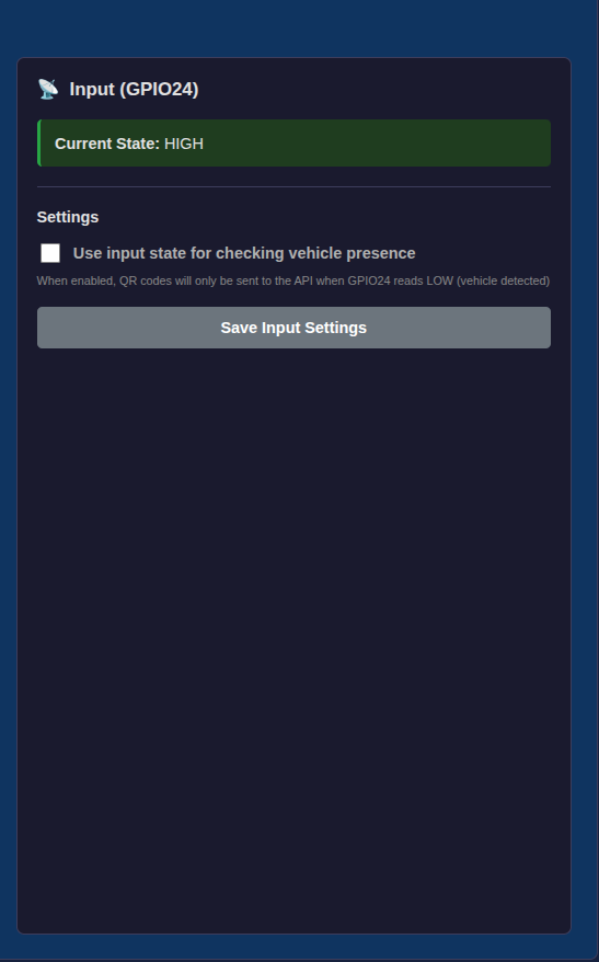
The input pin reads the state of an external vehicle detection sensor (typically an inductive loop). It reports either HIGH (no vehicle) or LOW (vehicle present).
Current State
HIGH = no car / LOW = car detected — see Fig.25 Input (GPIO24).
Vehicle Presence Check
Enable/Disable via the checkbox in Fig.25 Input (GPIO24). When enabled, QR codes are only processed when a vehicle is detected on the loop (GPIO24 reads LOW). This prevents the barrier from being opened when no car is present.
Inductive Loop
The inductive loop is a coil of wire buried in the pavement where cars stop. It connects to a loop detector module, which sends a signal to the device's INPUT wire (GPIO24).
When a car drives over the loop, the metal in the vehicle changes the magnetic field of the coil. The detector module senses this change and switches its output, telling the QR scanner that a vehicle is present.
Relay & Input HTTP API
The terminal exposes two HTTP endpoints so the relay (GPIO23) and input (GPIO24) can be controlled and read
directly over the network — for example by another system, a controller, or for testing. In the examples
below, replace 192.168.100.121 with the terminal's corect IP address if the default was changed.
1. /relay.php — Relay Control (GPIO23)
| Method | URL | Description |
|---|---|---|
| GET | /relay.php |
Check the current state |
| GET | /relay.php?state=1 |
Turn the relay on |
| GET | /relay.php?state=0 |
Turn the relay off |
| POST | /relay.php |
With JSON body {"state": 1} |
curl examples
# Check the current state
curl http://192.168.100.121/relay.php

# Turn the relay on
curl http://192.168.100.121/relay.php?state=1

# Turn the relay off
curl http://192.168.100.121/relay.php?state=0

# With authentication enabled
curl -u admin:secretpass http://192.168.100.121/relay.php?state=1

# With POST and JSON
curl -X POST \
  -H "Content-Type: application/json" \
  -d '{"state": 1}' \
  http://192.168.100.121/relay.php

# With POST + authentication
curl -u admin:secretpass \
  -X POST \
  -H "Content-Type: application/json" \
  -d '{"state": 1}' \
  http://192.168.100.121/relay.php
Response
{
  "relay": "on",
  "gpio23": 1,
  "initial_state": 0,
  "reset_time": 2
}-u admin:secretpass. The
reset_time and initial_state values in the response reflect the relay settings
configured in the dashboard.2. /input.php — Input Reading (GPIO24)
| Method | URL | Description |
|---|---|---|
| GET | /input.php |
Check the GPIO24 input state |
curl examples
# Check the input state
curl http://192.168.100.121/input.php
Response
{
  "gpio24_state": 1,
  "vehicle_presence_enabled": false,
  "description": "HIGH (active)"
}
Security Settings
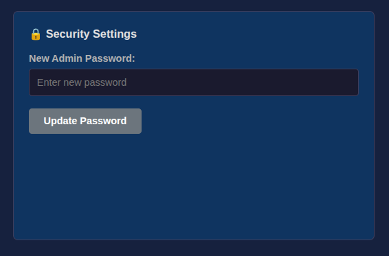
Allows changing the admin dashboard password. The dashboard is accessible at the device's IP address via a web browser on the local network — see Fig.26 Security Settings. After entering the new password, be sure to click Update Password for the change to take place.
Language Settings
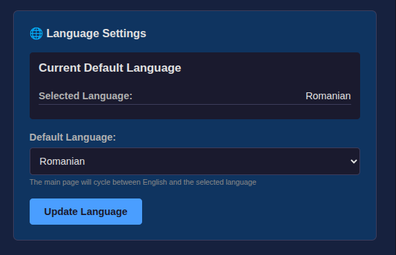
Sets the default language for the device's public-facing display. The main page cycles between English and the selected language (e.g. Romanian) — see Fig.27 Language Settings. After choosing the language, click Update Language to apply it.
Admin Activity Logs
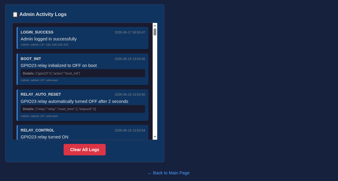
Displays a timestamped log of system events such as device boot, relay state changes, and admin logins. Useful for troubleshooting and monitoring. Logs can be cleared with the "Clear All Logs" button — see Fig.28 Admin Activity Logs.
System Management
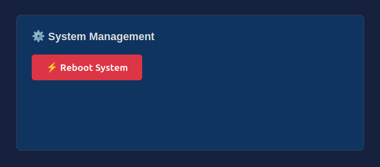
The System Management setting lets the administrator restart the access terminal. Pressing the Reboot System button reboots the device — see Fig.29 System Management.
There are two situations where a reboot is needed:
- After changing settings from a browser — if an administrator makes changes from a web browser (from another device on the network), the terminal must be rebooted for the changes to apply. If the changes are made directly on the terminal itself (on the touchscreen), the reboot is not necessary.
- After a firmware update — a reboot is necessary for the new firmware to take effect.
Physical Connectors
The device has two external connectors:
| Connector | Type | Purpose |
|---|---|---|
| Ethernet (RJ45) | Standard RJ45 port | Network connectivity and power delivery (PoE 802.3bt). A single Ethernet cable provides both data and power to the device. |
| I/O Connector | 4-pin circular connector | Carries the input and output signal wires for barrier control and vehicle detection. |
I/O Connector Pin Layout
| Pin | Function | Description |
|---|---|---|
| 1 | OUTPUT + | Relay signal to the barrier — connect to the barrier's "OPEN" or "TRIGGER" terminal. |
| 2 | OUTPUT − | Relay ground — connect to the barrier's ground terminal. |
| 3 | INPUT + | Vehicle detection signal — connect to the inductive loop detector's relay output. |
| 4 | INPUT − | Input ground — connect to the loop detector's ground. |